
Reconfigurable console mount

Active Publication Date: 2010-04-15
CARNEVALI JEFFREY D
View PDF45 Cites 11 Cited by
  • Summary
  • Abstract
  • Description
  • Claims
  • Application Information

AI Technical Summary

Benefits of technology

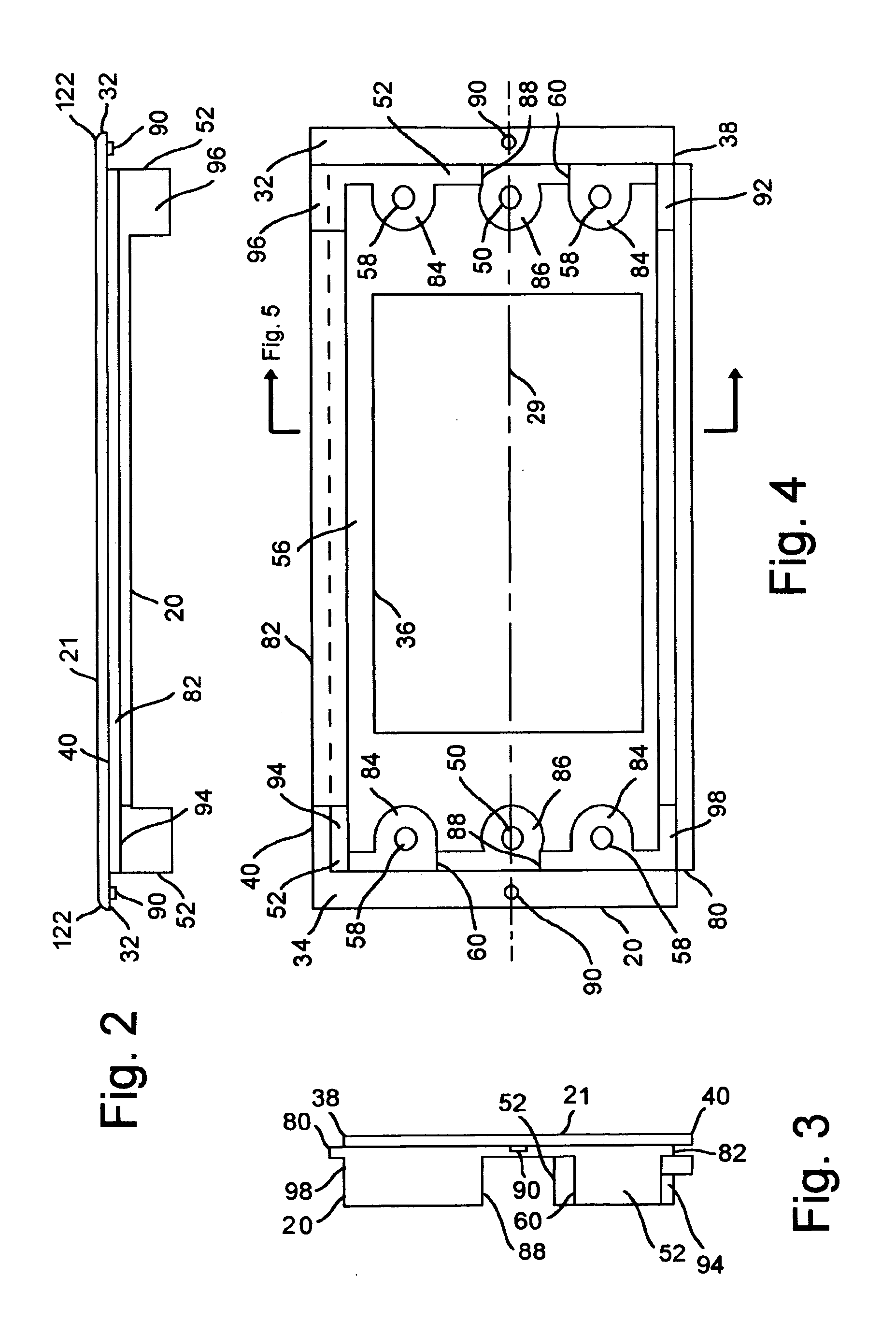
[0010]The utilization of off-the-shelf blank face plates also allows specific positioning of the one or more cutouts in each face plate so that the cutout for the same equipment piece is easily centered in one face plate, while the cutout for the same equipment piece is asymmetrically positioned in another face plate for the same or a different order. Nor do the cutouts have to be similarly shaped, a round cutout for a meter or electrical outlet is easily placed beside a square cutout for a radio and a keyhole cutout for a switch or dial or yet an irregular cutout for a proprietary equipment piece. A speaker grille cutout and associated fastener hole cutouts can be cut into off-the-shelf blank face plates as easily as a rectangular cutout for a standard radio equipment piece. The forming of the cutouts thereby transforms any number of off-the-shelf blank face plates into equipment mounting face plates that are either standardized or customized to receive a selected equipment piece. The forming of the cutouts is optionally accomplished by the original manufacturer of the off-the-shelf blank face plates, else by any of the distributor, the wholesaler, retailer, installer or end user of the console. For example, the distributor, the wholesaler, retailer, installer or end user of the console can form the cutouts in the blank face plate by sawing or drilling using conventional home shop tools. Alternatively, the original manufacturer may partially form one or a series of cutouts in the face plate, for example by cutting from the interior surface thereof part way through the face plate thickness to the outer surface.
[0012]This process of forming and storing blank face plates of a few or several integer widths, then transforming the off-the-shelf blank face plates into equipment mounting face plates by forming therein cutouts of desired size and shape and bundling the resulting equipment mounting panels with pairs of end panels and side panels and, optionally, one or more one or more blank face plates to form a custom console results in a truly modular console system that: 1) minimizes inventory, 2) permits filling of large or small orders for different configurations of blank face and equipment mounting face plates with custom cutouts, and 3) permits forming any size cutout to fit different equipment pieces of any size or shape and quantity.

Problems solved by technology

Systems employing the conventional equipment box described above suffer from a number of problems associated with the structure of the box.
Unfortunately, the equipment mounting brackets fasten to the box side panels using screws so the equipment is not easily repositioned within the bore or changed out for different pieces of equipment.
The conventional equipment box configuration described above makes it more difficult to remove a piece of equipment from this box, or reposition it along closer to one or another of the end panels.

Method used


Image

  • Reconfigurable console mount
  • Reconfigurable console mount
  • Reconfigurable console mount

Examples


Embodiment Construction

[0027]In the Figures, like numerals indicate like elements.

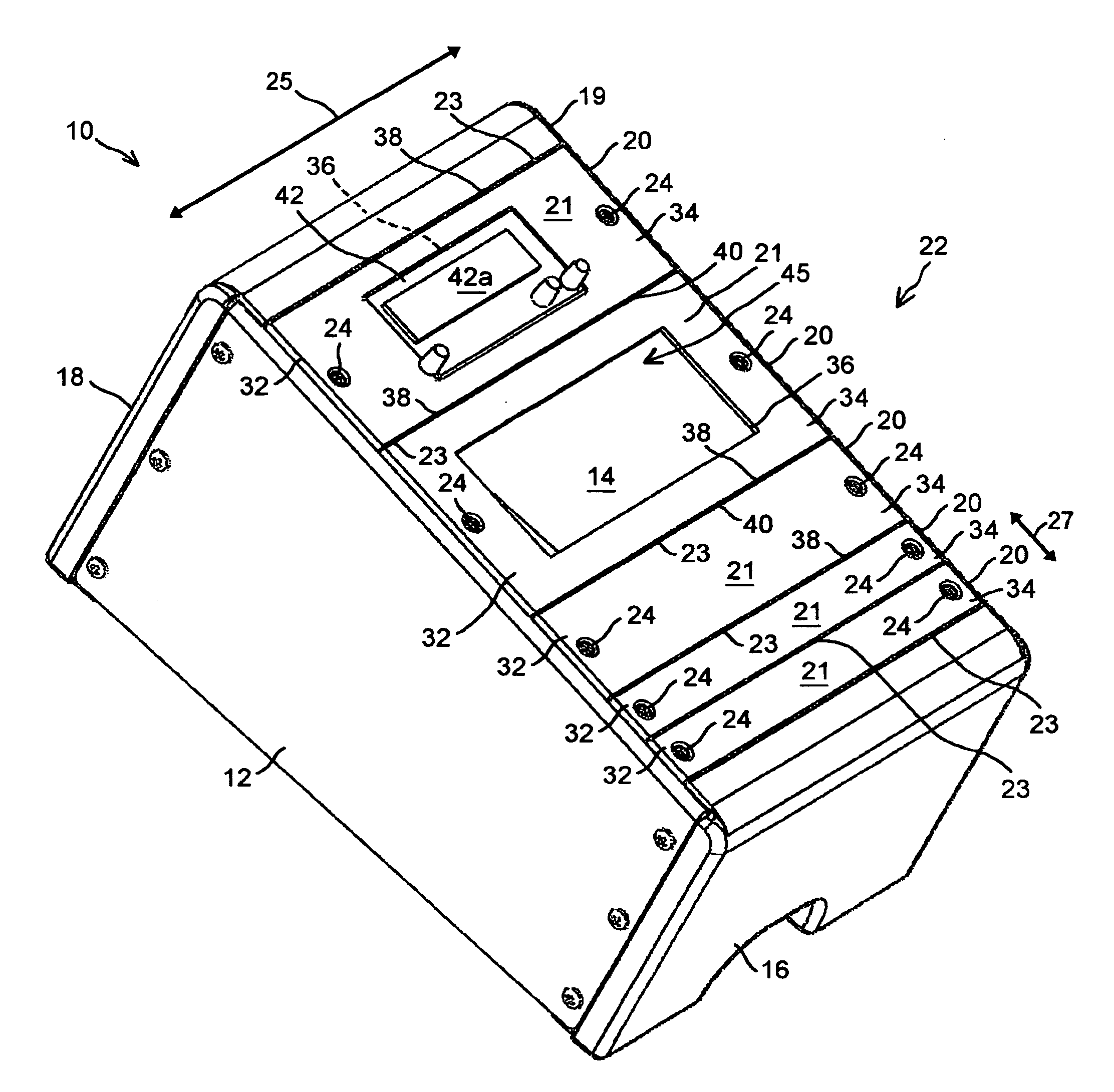
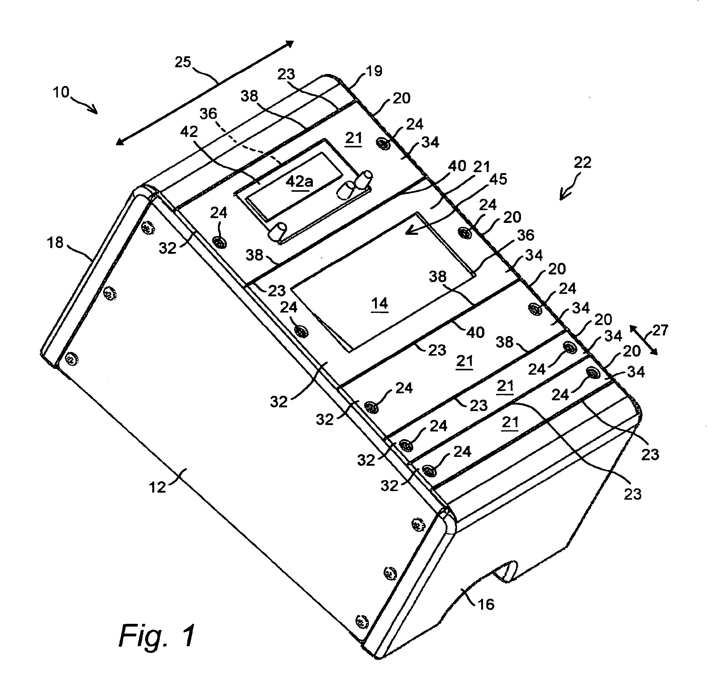
[0028]FIG. 1 is a perspective view that illustrates a novel reconfigurable vehicle console 10 having opposing first and second substantially rigid side panels 12 and 14 each configured for being secured to the drive shaft floor hump of the vehicle using, for example using an interface plate attached to the hump and having a plurality of fastener holes spaced along side flanges arranged along the hump. The side panels 12, 14 are substantially rigidly interconnected with opposing first and second substantially rigid end panels 16 and 18. The side panels 12, 14 and end panels 16, 18 are either integrated in a single continuous frame 19, else joined together to form the console frame 19.

[0029]The end panels 16, 18 are substantially the same width such that the side panels 12, 14 are spaced apart a substantially uniform or constant distance between the end panels 16, 18, thereby forming the substantially rectangular console frame...


PUM

PropertyMeasurementUnit
Widthaaaaaaaaaa
Distanceaaaaaaaaaa

Abstract

A reconfigurable vehicle console having a plurality of interchangeable overlapping blank and equipment mounting face plates, including both tongue-and-groove joints between adjacent face plates, as well as optional lap joints.

Description

[0001]This application is a Continuation-in-part co-pending patent application Ser. No. 12 / 287,622 filed in the name of the same inventor on Oct. 10, 2008, which is incorporated herein by reference.FIELD OF THE INVENTION[0002]The present invention relates to vehicle consoles and in particular to one that provides novel reconfigurable equipment mounting features, the console being mountable within a vehicle driver compartment to support either mechanical, electrical or electro-mechanical equipment in a location easily accessible to an operator of the vehicle.BACKGROUND OF THE INVENTION[0003]Police officers, public safety officers, firefighters, paramedics and the like carry various types of equipment in their vehicles. Several pieces of equipment are often carried in a single vehicle, and the driver often needs to operate the equipment while simultaneously driving the vehicle. Thus, various devices exist to secure multiple pieces of equipment within a vehicle so that they are accessi...

Claims


Application Information

Patent Timeline
IPC IPC(8): B60R99/00B32B37/00
CPCB60R11/02Y10T29/49947B60R2011/0045B60R2011/0007
Inventor CARNEVALI, JEFFREY D.
Owner CARNEVALI JEFFREY D
Learn More