Rotary encoder and method of assembling the same

a technology of rotary encoder and assembler, which is applied in the direction of optical measurement, optical radiation measurement, instruments, etc., can solve the problems of long production time and many hours of these processes, and achieve the effects of convenient centering, high accuracy and easy assembly of the rotary scal

Active Publication Date: 2013-07-16
CANON KK +1
View PDF8 Cites 12 Cited by
  • Summary
  • Abstract
  • Description
  • Claims
  • Application Information

AI Technical Summary

Benefits of technology

[0007]In is an object of the present invention to provide a rotary encoder, which enables easy centering between a rotary scale and a hub, and further enables easy assembling of the rotary scale and the hub with high accuracy, and to provide a method of assembling the rotary encoder.
[0011]According to the present invention, there may be obtained a rotary encoder, which enables easy centering between the rotary scale and the hub, and further enables easy assembling of the rotary scale and the hub with high accuracy, and a method of assembling the rotary encoder.

Problems solved by technology

However, because the rotary scale is disc-shaped and difficult to determine its mounting phase, there is a problem in that, in order to align the original point of the rotary scale with the hub with regard to the original point of the angular direction and to assemble the rotary scale and the hub, many hours for these processes are required.
Further, there is a problem in that centering between the rotary scale and the hub also requires many hours or needs improvement for accuracy of an inner diameter of the rotary scale, which leads to prolonged production time.

Method used


Image

  • Rotary encoder and method of assembling the same
  • Rotary encoder and method of assembling the same
  • Rotary encoder and method of assembling the same

Examples


first embodiment

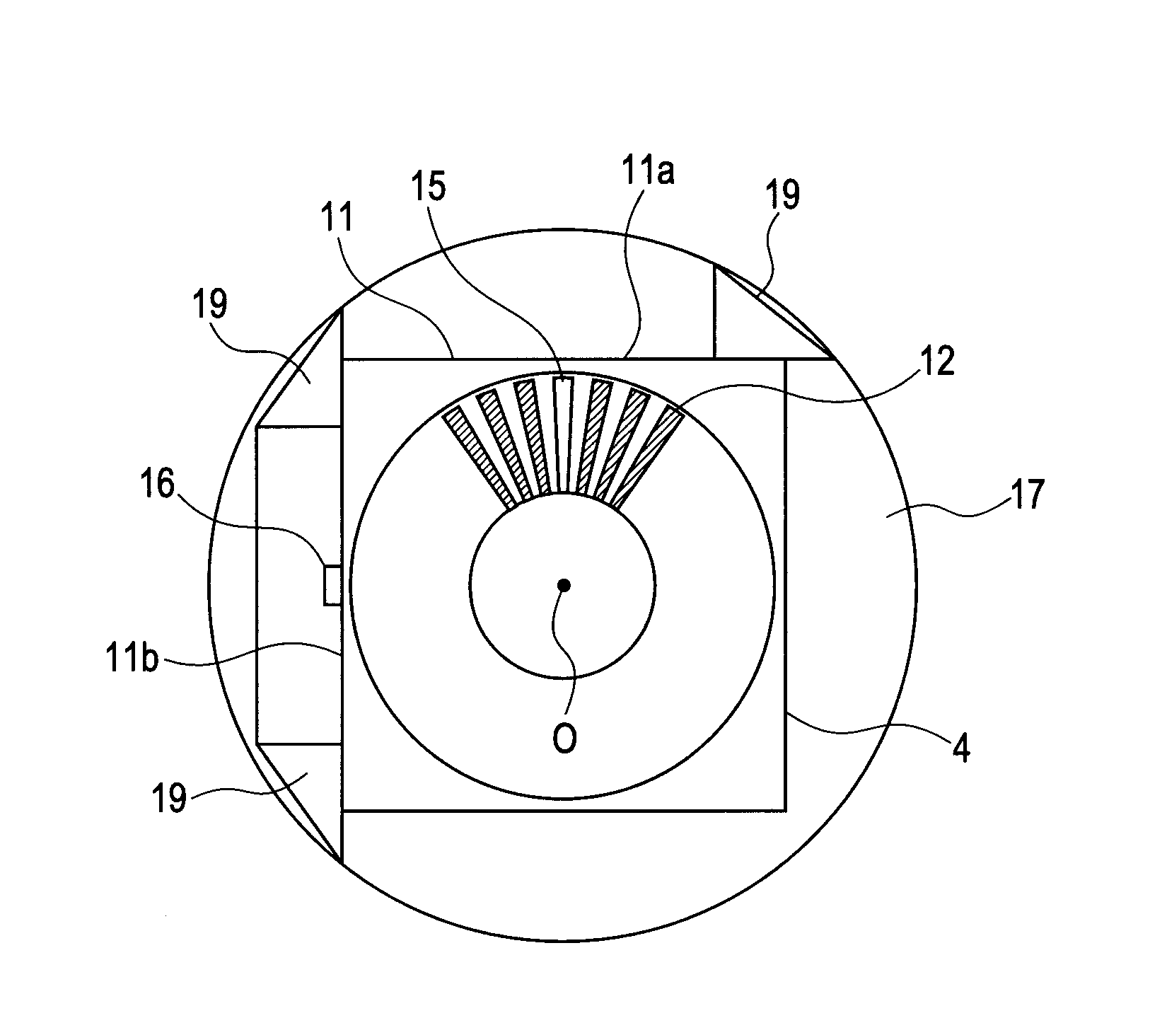
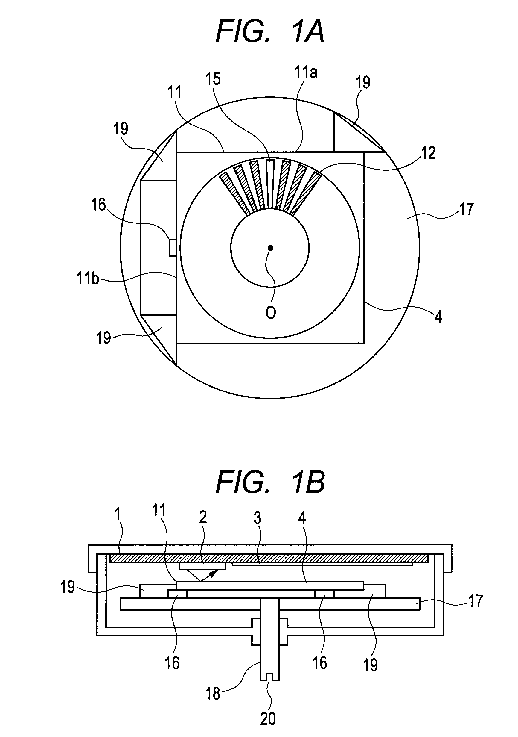
[0027]FIGS. 1A and 1B are a main portion top view and a partial side sectional view, respectively, illustrating a rotating unit of the rotary encoder according to the present invention. In this embodiment, the rotary scale 4 has a square outer shape and is made of silicon (Si). The rotary scale 4 is of a reflecting type having silicon as a base material, using aluminum for a reflection film, and being fabricated by a semiconductor manufacturing process including deposition, exposure, etching, etc. The square rotary scale 4 is adhered to three projections 19 having taller height provided on the hub 17 as a rotating unit made of a resin under a state in which the rotary scale 4 is butted against and aligned with the three projections 19. The shaft (rotating shaft) 18 made of a metal is press-fitted into the hub 17.

[0028]The rotary scale 4 is provided with the continuous patterns 12 and the discontinuous portion (discontinuous pattern) 15, for detecting the rotation information. The di...

fourth embodiment

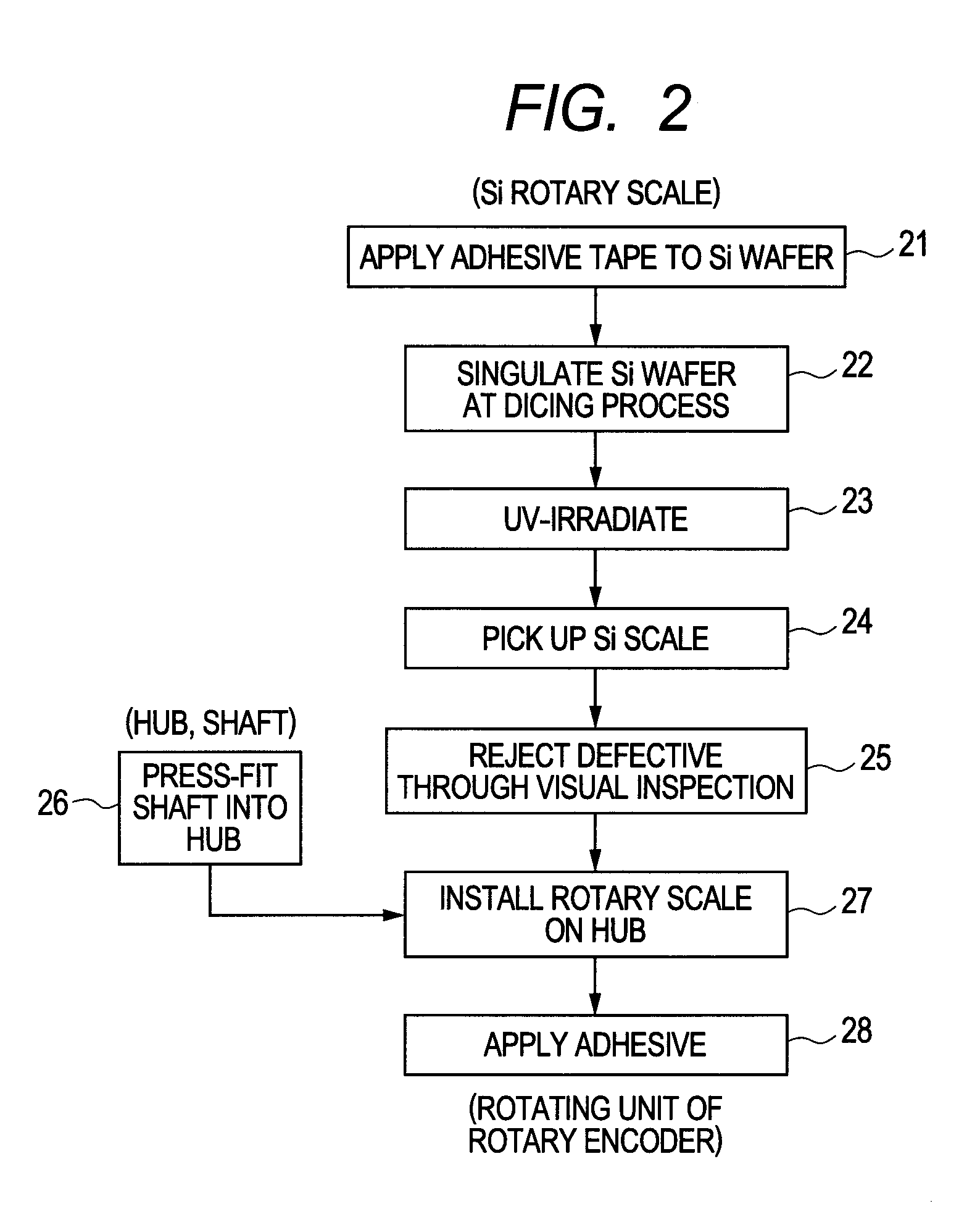
[0038]Hereinafter, a method of assembling a rotary encoder according to the present invention is described. The method of assembling the rotary encoder of the present invention is performed with reference to an orientation flat 32 of the silicon wafer 31. The predetermined pattern including the continuous patterns 12 and the discontinuous pattern (rotational angle original point) 15 is formed with reference to the pattern center (rotation center), and the rotary scale having a polygonal outer shape is cut out. The rotational angle original point is defined with reference to the at least one side 11a of the sides of the polygonal outer shape. The rotary scale 4 thus cut out is mounted to the hub 17, which is to rotate coaxially with the rotary scale 4, in such a manner that the rotary scale 4 abuts the projections 19 for positioning provided on the hub 17, so as to assemble the rotary encoder.

[0039]Position information (positional relationship) is measured among two sides 11a, 11b of...

fifth embodiment

[0047]In a method of assembling a rotary encoder according to the present invention, the positional relationship is measured between the rotating shaft 18 and the projections 19 for butting the rotary scale with respect to the shaft center of the hub 17. In this case, the rotary scale is offset in a direction to compensate a displacement amount thus determined, and subsequently the rotary scale is cut from a silicon wafer so as to assemble the rotary encoder.

[0048]FIG. 10 is an explanatory diagram illustrating the method of assembling the rotary encoder according to the fifth embodiment of the present invention. In FIG. 10, Xh denotes a distance between the center of the hub 17 and the butting portion of the projection 19 in an X-axis direction, and Yh denotes a distance between the center of the hub 17 and the butting portion of the projection 19 in a Y-axis direction. Xs denotes a distance between the center of the rotary scale 4 and the butting portion of the projection 19 in the...


PUM

PropertyMeasurementUnit
distancesaaaaaaaaaa
rotational angleaaaaaaaaaa
shapeaaaaaaaaaa

Abstract

Provided is a rotary encoder, including: a rotary scale, which has a predetermined pattern including continuous patterns and a rotational angle original point formed thereon with reference to a pattern center, has a polygonal outer shape, and has the rotational angle original point defined with reference to at least one side of sides of the polygonal outer shape; a hub, which includes projections for abutting the sides of the polygonal outer shape of the rotary scale and positioning the rotary scale; a rotating shaft, which is press-fitted into the hub and rotates coaxially with the pattern center of the rotary scale; and detecting units for irradiating the rotary scale with light and detecting the light reflected by the rotary scale.

Description

BACKGROUND OF THE INVENTION[0001]1. Field of the Invention[0002]The present invention relates to a rotary encoder for detecting rotation information such as a rotational speed and a rotational angle of an object to be detected, in particular a rotary encoder suitable for detecting a rotational angle original point of the object to be detected.[0003]2. Description of the Related Art[0004]As a rotary encoder, there is known an optical rotary encoder adapted for detecting absolute position information among rotation information about an object to be detected (Japanese Patent Application Laid-Open No. 2006-214929). For example, in a reflecting type rotary encoder, light emitted from a light emitting element such as an LED provided on a detecting head is reflected by a rotary scale, the returning light is received by a light detecting element such as a phototransistor, and lights and darks of the received light are counted, thereby measuring the rotation information about the rotary scal...

Claims


Application Information

Patent Timeline
Patent Type & Authority Patents(United States)
IPC IPC(8): G01D5/347G01D5/36
CPCG01D5/34715Y10T29/49002
Inventor WATANABE, IKUOIGAKI, MASAHIKONAGURA, CHIHIROKOZUKA, HIRAKUHAMASAKI, SATORUOGURA, MAKOTONAGAO, TSUTOMUYOKOYAMA, YASUJI
Owner CANON KK
Why Eureka
Try Eureka