Lathe chuck capable of preventing axial sliding of workpiece
What is Al technical title?
Al technical title is built by PatSnap Al team. It summarizes the technical point description of the patent document.
An axial sliding, lathe technology, applied in the direction of chucks, turning equipment, manufacturing tools, etc., can solve the problems of reducing machining accuracy, affecting product quality, axial sliding, etc., to improve machining accuracy, good fixing effect, convenient The effect of center positioning
Active Publication Date: 2016-09-28
西安朋邦工贸有限公司
View PDF6 Cites 10 Cited by
Summary
Abstract
Description
Claims
Application Information
AI Technical Summary
This helps you quickly interpret patents by identifying the three key elements:
Problems solved by technology
Method used
Benefits of technology
Problems solved by technology
[0006] The present invention overcomes that the chuck of the existing lathe usually adopts a traditional structure. When the lathe processes the center hole or end face hole of the workpiece, the workpiece clamped by the existing chuck is prone to axial sliding, resulting in loosening of the workpiece and reducing the machining cost. Accuracy, the shortcoming that affects the quality of the product, the technical problem to be solved by the present invention is to provide a kind of chuck that prevents the workpiece from axially sliding lathe
Method used
Image
Click on the blue label to locate the original text in one second.
Reading with bidirectional positioning of images and text.
Examples
Embodiment 1
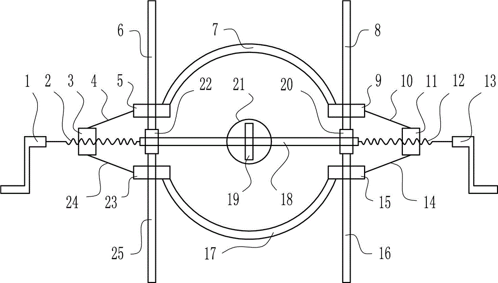
[0016] A chuck for lathes that prevent workpieces from sliding axially, such as figure 1 As shown, it includes left rocker 1, left screw rod 2, left nut 3, connecting rod Ⅲ4, slider Ⅲ5, slider Ⅲ6, upper arc-shaped fixing plate 7, slider Ⅱ8, slider Ⅱ9, connecting rod Ⅱ10, Right nut 11, right screw rod 12, right rocker 13, connecting rod I14, slider I15, slider I16, lower arc-shaped fixing plate 17, cross bar 18, fixing block 19, right bearing 20, connecting shaft 21, left Bearing 22, slide block Ⅳ 23, connecting rod Ⅳ 24 and slide bar Ⅳ 25; the left side of the right crank handle 13 is provided with a right screw mandrel 12, and the right screw mandrel 12 is connected with the right crank handle 13; the right screw mandrel 12 is provided with a right nut 11. The right nut 11 is matched with the right screw rod 12; the connecting rod I14 is arranged under the right nut 11, and the connecting rod I14 and the right nut 11 are arranged to be hingedly connected; the left side of the...
PUM
Abstract
The invention relates to a chuck, in particular to a lathe chuck capable of preventing axial sliding of a workpiece. According to the technical aim, the lathe chuck capable of preventing axial sliding of the workpiece comprises a left rocking handle, a left lead screw, a left nut, a connecting rod III, a sliding block III, a sliding rod III, an upper arc fixed plate, a sliding rod II, a sliding block II, a connecting rod II, a right nut, a right lead screw, a right rocking handle, a connecting rod I, a sliding block I, a sliding rod I, a lower arc fixed plate, a cross rod, a fixed block, a right bearing, a connecting shaft, a left bearing, a sliding block IV, a connecting rod IV and a sliding rod IV. The right lead screw is arranged on the left side of the right rocking handle. According to the lathe chuck capable of preventing axial sliding of the workpiece, by means of the structure of the vertically symmetric arc fixed plates and cooperation of the nuts and the lead screws, the center of the workpiece can be located conveniently.
Description
technical field [0001] The invention relates to a chuck, in particular to a chuck used for preventing workpieces from axially sliding on a lathe. Background technique [0002] A chuck is a mechanical device used to clamp a workpiece on a machine tool. A machine tool accessory that clamps and positions workpieces by using the radial movement of movable jaws evenly distributed on the chuck body. The chuck is generally composed of three parts: the chuck body, the movable jaw and the jaw driving mechanism. The minimum diameter of the chuck body is 65mm, and the maximum can reach 1500mm. There is a through hole in the center to pass the workpiece or bar; the back has a cylindrical or short tapered structure, which is connected directly or through the flange to the end of the machine tool spindle. . Chucks are usually installed on lathes, cylindrical grinders and internal grinders, and can also be used with various indexing devices for milling machines and drilling machines. ...
Claims
Application Information
Patent Timeline
Application Date:The date an application was filed.
Publication Date:The date a patent or application was officially published.
First Publication Date:The earliest publication date of a patent with the same application number.
Issue Date:Publication date of the patent grant document.
PCT Entry Date:The Entry date of PCT National Phase.
Estimated Expiry Date:The statutory expiry date of a patent right according to the Patent Law, and it is the longest term of protection that the patent right can achieve without the termination of the patent right due to other reasons(Term extension factor has been taken into account ).
Invalid Date:Actual expiry date is based on effective date or publication date of legal transaction data of invalid patent.