Card smashing machine

A card shredding and knife shaft technology, applied in the field of card shredders, can solve the problems of card shredding, environmental pollution, large thickness, etc., and achieve better cutting effect, avoid insufficient strength, and high strength

Active Publication Date: 2016-07-20
常州川刃办公设备有限公司
View PDF7 Cites 2 Cited by
  • Summary
  • Abstract
  • Description
  • Claims
  • Application Information

AI Technical Summary

Problems solved by technology

[0002] In modern society, bank cards are widely used, and there are countless types of commercial banks. However, the recycling and destruction of waste bank cards is an extremely complicated task. Because the material of bank cards is relatively hard, incineration will cause serious problems. environmental pollution problems; facing the same problem are CDs, SD cards, circuit boards, etc. When the above products are recycled and destroyed, they also need to be cut into fragments or even particles; The operating principle of the paper shredder is that a large number of cutting blades and spacer rings are placed on the rotating knife shaft,

Method used


Image

  • Card smashing machine
  • Card smashing machine
  • Card smashing machine

Examples


Embodiment 1

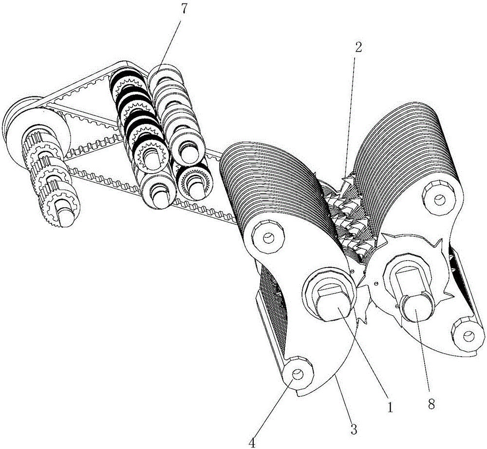
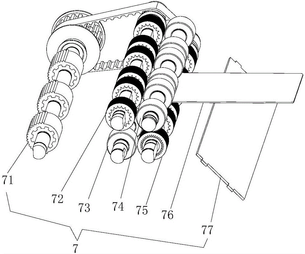
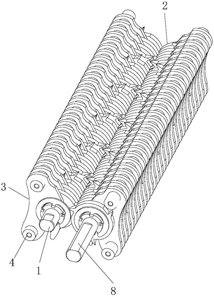
[0044] Such as Figure 1 to Figure 2 As shown, the card shredder of this embodiment includes a transmission assembly 7 and a cutter shaft assembly; the transmission assembly 7 includes a friction separation wheel 71 arranged below the stacked cards, and behind the friction separation wheel 71 is provided a vertical parallel arrangement. The first driving wheel 72 and the first driven wheel 73, between the first driving wheel 72 and the first driven wheel 73, be provided with the gap that is suitable for the card to be cut to pass through; The second driving wheel 74 and the second driven wheel 75 that are arranged in parallel up and down are arranged, be provided with the gap that is suitable for the card to be cut to pass between the second driving wheel 74 and the second driven wheel 75; The second driving wheel 74 and the second The rear of the driven wheel 75 is provided with an upper baffle plate 76 and a lower baffle plate 77, the upper baffle plate 76 is arranged horizo...

Embodiment 2

[0051] On the basis of Embodiment 1, the card shredder of this embodiment has the following deformations:

[0052] Such as Figure 12 As shown, the ring-shaped blade 2 of the present embodiment is made up of the left ring-shaped blade and the right ring-shaped blade that are all identical in structure and shape, and when the two ring-shaped blades are close together, the tip of the knife is also put together, The cross-section at the top of the knife point 22 formed is A-type; as Figure 13 As shown, the outer ring wall of the annular spacer 6 is provided with a V-shaped groove 62 along the circumference, as shown in the assembly. Figure 14 The A-shaped top of the shown knife point 22 is in close contact with the bottom of the V-shaped groove 62 .

Embodiment 3

[0054] On the basis of Embodiment 1, the card shredder of this embodiment has the following deformations:

[0055] Such as Figure 15 As shown, the ring-shaped blade 2 of the present embodiment is made up of the left ring-shaped blade and the right ring-shaped blade that are all identical in structure and shape, and when the two ring-shaped blades are close together, the tip of the knife is also put together, The section at the top of the formed knife point 22 is V-shaped; as Figure 16 As shown, the cross-section of the outer ring wall of the annular spacer 6 is set in an inverted V shape, so that a W-shaped recess is formed in the circumferential direction between the outer ring wall of the annular spacer 6 and the annular blades 2 on adjacent sides. Slot 62, assembled as Figure 17 The A-shaped top of the knife point 22 shown is adjacent to the bottom of the inverted V-shaped groove 62 .


PUM

PropertyMeasurementUnit
Thicknessaaaaaaaaaa
Thicknessaaaaaaaaaa
Hardnessaaaaaaaaaa

Abstract

The invention relates to a card smashing machine. The card smashing machine comprises a transmission assembly and a cutter shaft assembly; the cutter shaft assembly comprises two cutter shafts which are arranged in a spaced manner in parallel, and each cutter shaft is provided with a plurality of annular space rings and a plurality of annular blades with cutter noses; the position, between every two adjacent annular blades, on each cutter shaft is provided with one annular space ring, so that gaps are reserved between the adjacent annular blades; a groove is formed in the outer annular wall of each annular space ring in the circumferential direction of the annular space ring, the cutter noses of the annular blades on one cutter shaft extend to the corresponding grooves of the annular space rings on the other cutter shaft, and the cutter noses and the grooves are distributed in an adjoining manner; a discharging opening of the transmission assembly is formed above the gap between the opposite inner sides of the two cutter shafts; and when the card smashing machine is used, the two cutter shafts reversely rotate to the opposite inner sides, and the annular blades are driven to conduct cutting smashing on cards entering the position between the two cutter shafts. A groove is formed between every two adjacent annular blades, the top ends of the cutter noses are closely arranged along the grooves, the distances between the cutter noses and the corresponding cutter shafts can be reduced, and the diameter of the cutter shafts can be increased under the same conditions.

Description

technical field [0001] The invention relates to the technical field of card crushing equipment, in particular to a card crushing machine. Background technique [0002] In modern society, bank cards are widely used, and there are countless types of commercial banks. However, the recycling and destruction of waste bank cards is an extremely complicated task. Because the material of bank cards is relatively hard, incineration will cause serious problems. environmental pollution problems; facing the same problem are CDs, SD cards, circuit boards, etc. When the above products are recycled and destroyed, they also need to be cut into fragments or even particles; The operating principle of the paper shredder is that a large number of cutting blades and spacer rings are placed on the rotating knife shaft, and the two parallel and relatively rotating knife shafts are driven by a motor and a transmission gear set. Cut into thin strips. Because the card is thicker and harder than ord...

Claims


Application Information

Patent Timeline
IPC IPC(8): B02C18/14B02C18/16B02C18/18B02C18/24B02C18/22
CPCB02C18/0007B02C18/142B02C18/145B02C18/18B02C18/182B02C18/2283B02C18/24B02C2018/0015B02C2018/0038
Inventor 徐罗斌
Owner 常州川刃办公设备有限公司
Why Eureka
Try Eureka