Lathe chuck for preventing workpiece from axially sliding
What is Al technical title?
Al technical title is built by PatSnap Al team. It summarizes the technical point description of the patent document.
A technology of axial sliding and workpiece, which is applied in the direction of chucks, metal processing machinery parts, manufacturing tools, etc., can solve the problems of reducing processing accuracy, economic loss of enterprises, and scrapping of products in batches, and achieves high processing accuracy, convenient operation, The effect of reducing the scrap rate
Active Publication Date: 2016-10-12
CHONGQING SHUAIBANG MACHINERY CO LTD
View PDF5 Cites 2 Cited by
Summary
Abstract
Description
Claims
Application Information
AI Technical Summary
This helps you quickly interpret patents by identifying the three key elements:
Problems solved by technology
Method used
Benefits of technology
Problems solved by technology
[0004] The chuck of the existing lathe usually adopts the traditional structure. When the lathe processes the center hole or the end face of the workpiece, the workpiece held by the existing chuck is prone to axial sliding, resulting in loosening of the workpiece, reducing the processing accuracy and affecting the product. quality, and even lead to batch scrapping of products, causing huge economic losses to the enterprise
Method used
Image
Click on the blue label to locate the original text in one second.
Reading with bidirectional positioning of images and text.
Examples
Embodiment 1
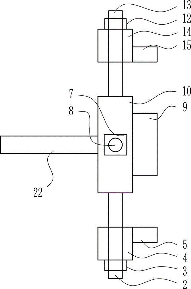
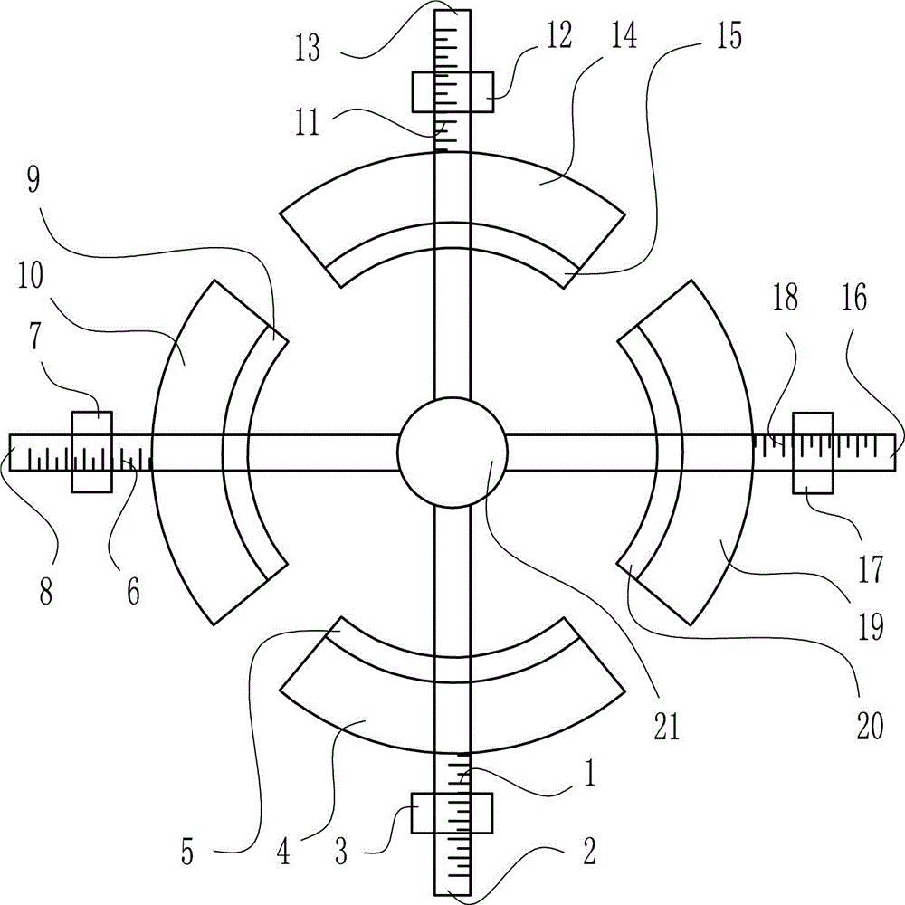
[0019] A chuck for lathes to prevent axial sliding of workpieces, such as Figure 1-2As shown, it includes guide rod Ⅳ2, nut Ⅳ3, fan-shaped fixing plate Ⅳ4, fan-shaped fixing block Ⅳ5, nut Ⅲ7, guide rod Ⅲ8, fan-shaped fixing block Ⅲ9, fan-shaped fixing plate Ⅲ10, nut Ⅱ12, guide rod Ⅱ13, fan-shaped fixing plate Ⅱ14 , fan-shaped fixing block II15, guide rod I16, nut I17, fan-shaped fixing plate I19, fan-shaped fixing block I20, disc-shaped electromagnet 21 and connecting shaft 22; The rod Ⅰ16 is connected with the disc-shaped electromagnet 21; the guide rod Ⅰ16 is provided with a thread, the guide rod Ⅰ16 is provided with a nut Ⅰ17, and the nut Ⅰ17 and the guide rod Ⅰ16 are threadedly connected; the guide rod Ⅰ16 is provided with a fan-shaped fixing plate Ⅰ19 , the fan-shaped fixing plate I19 and the guide rod I16 are set to be connected in a movable manner; the fan-shaped fixing plate I19 is arranged between the disc-shaped electromagnet 21 and the nut I17, and the fan-shaped f...
PUM
Abstract
The invention relates to a chuck, in particular to a lathe chuck for preventing a workpiece from axially sliding. The technical purpose of the invention is to provide the lathe chuck for preventing a workpiece from axially sliding. In order to realize the technical purpose, the lathe chuck for preventing a workpiece from axially sliding is provided and comprises a guide rod IV, a nut IV, a fan-shaped fixing plate IV, a fan-shaped fixing block IV, a nut III, a guide rod III, a fan-shaped fixing block III, a fan-shaped fixing plate III, a nut II, a guide rod II, a fan-shaped fixing plate II, a fan-shaped fixing block II, a guide rod I, a nut I, a fan-shaped fixing plate I, a fan-shaped fixing block I, a disc-shaped electromagnet and a connecting shaft. The guide rod I is arranged on the right side of the disc-shaped electromagnet. The lathe chuck, provided by the invention, for preventing a workpiece from axially sliding is simple and novel in structure, reasonable in design, good in workpiece fixing effect, high in workpiece machining precision and capable of preventing a workpiece from axially sliding during workpiece machining.
Description
technical field [0001] The invention relates to a chuck, in particular to a chuck for lathes which prevents workpieces from sliding axially. Background technique [0002] The chuck is a mechanical device used to clamp the workpiece on the machine tool. It is a machine tool accessory that uses the radial movement of the movable jaws evenly distributed on the chuck body to clamp and position the workpiece. The chuck is generally composed of three parts: the chuck body, the movable jaw and the jaw driving mechanism. The minimum diameter of the chuck body is 65mm, and the maximum can reach 1500mm. There is a through hole in the center to pass the workpiece or bar; the back has a cylindrical or short tapered structure, which is connected directly or through the flange to the end of the machine tool spindle. . Chucks are usually installed on lathes, cylindrical grinders and internal grinders, and can also be used with various indexing devices for milling machines and drilling ma...
Claims
Application Information
Patent Timeline
Application Date:The date an application was filed.
Publication Date:The date a patent or application was officially published.
First Publication Date:The earliest publication date of a patent with the same application number.
Issue Date:Publication date of the patent grant document.
PCT Entry Date:The Entry date of PCT National Phase.
Estimated Expiry Date:The statutory expiry date of a patent right according to the Patent Law, and it is the longest term of protection that the patent right can achieve without the termination of the patent right due to other reasons(Term extension factor has been taken into account ).
Invalid Date:Actual expiry date is based on effective date or publication date of legal transaction data of invalid patent.