Heat radiation equipment

A technology for cooling equipment and equipment, applied in mechanical equipment, cooling/ventilation/heating renovation, instruments, etc., can solve problems such as cooling performance decline, fan blade and base collision, etc.

Active Publication Date: 2016-11-16
LENOVO (BEIJING) CO LTD
View PDF5 Cites 6 Cited by
  • Summary
  • Abstract
  • Description
  • Claims
  • Application Information

AI Technical Summary

Problems solved by technology

The existing technology has at least the following problems: with the increase of power consumption of the components, it is necessary to increase the rotatio

Method used


Image

  • Heat radiation equipment
  • Heat radiation equipment
  • Heat radiation equipment

Examples


Embodiment Construction

[0025] In order to understand the characteristics and technical contents of the embodiments of the present invention in more detail, the implementation of the embodiments of the present invention will be described in detail below in conjunction with the accompanying drawings. The attached drawings are only for reference and description, and are not intended to limit the embodiments of the present invention.

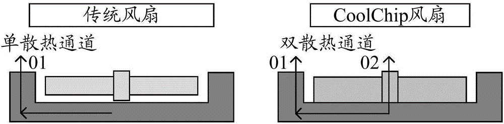
[0026] refer to figure 1 ,Such as figure 1 The diagram on the left is a schematic diagram of the heat dissipation channel of a traditional fan. The blades of a traditional fan are generally made of plastic material, and the heat dissipation channel of a traditional fan is a single heat dissipation channel. Such as figure 1 The figure on the right is a schematic diagram of the heat dissipation channel of the heat dissipation device in the embodiment of the present invention. The heat dissipation device in the embodiment of the present invention can also be called coolchip...


PUM


Abstract

The invention discloses heat radiation equipment. The heat radiation equipment comprises a fan and a base, wherein the fan is composed of a set of blades arranged surrounding a rotary shaft. First sides of the set of blades are all fixedly connected with a first surface of a base plate. A first protruding structure is arranged on a second surface of the base plate. A second protruding structure is arranged on a first surface of the base. The fan is arranged on the base. The first protruding structure keeps a first distance away from the first surface of the base through supporting with the rotary shaft. When the rotary shaft is adjusted to a second position from a first position, the rotary shaft drives the fan to move towards a first direction, and the first distance between the first protruding structure and the first surface of the base is increased. When the rotary shaft is adjusted to the first position from the second position, the rotary shaft drives the fan to move towards a second direction, and the first distance between the first protruding structure and the first surface of the base is decreased.

Description

technical field [0001] The invention relates to heat dissipation technology, in particular to a heat dissipation device. Background technique [0002] Coolchip is a new cooling solution that uses metal fans instead of traditional fans to provide better cooling and noise performance. [0003] In Coolchip, the smaller the gap between the fan blade and the heat dissipation base, the better the heat dissipation noise characteristics obtained by the low fan speed. There are at least the following problems in the prior art: as the power consumption of components increases, it is necessary to increase the speed to further improve the heat dissipation performance. The gap between the leaf and the heat dissipation base, the heat dissipation performance will decrease at low speeds. Contents of the invention [0004] In order to solve the above technical problem, an embodiment of the present invention provides a heat dissipation device. [0005] The heat dissipation device provide...

Claims


Application Information

Patent Timeline
IPC IPC(8): F04D29/32F04D29/64F04D29/02H05K7/20G06F1/20
CPCH05K7/20G06F1/20G06F1/203F04D29/023F04D29/325F04D29/642F04D29/644
Inventor 马驰州田婷
Owner LENOVO (BEIJING) CO LTD
Why Eureka
Try Eureka