Image enhancement method and device
An image enhancement and image technology, applied in the field of image processing, can solve the problems of missed diagnosis, misdiagnosis, and inconvenient diagnosis by doctors, and achieve the effect of enhancing subtle details and edges, reducing the probability of missed diagnosis or misdiagnosis, and improving quality.
- Summary
- Abstract
- Description
- Claims
- Application Information
AI Technical Summary
Problems solved by technology
Method used
Image
Examples
Embodiment 1
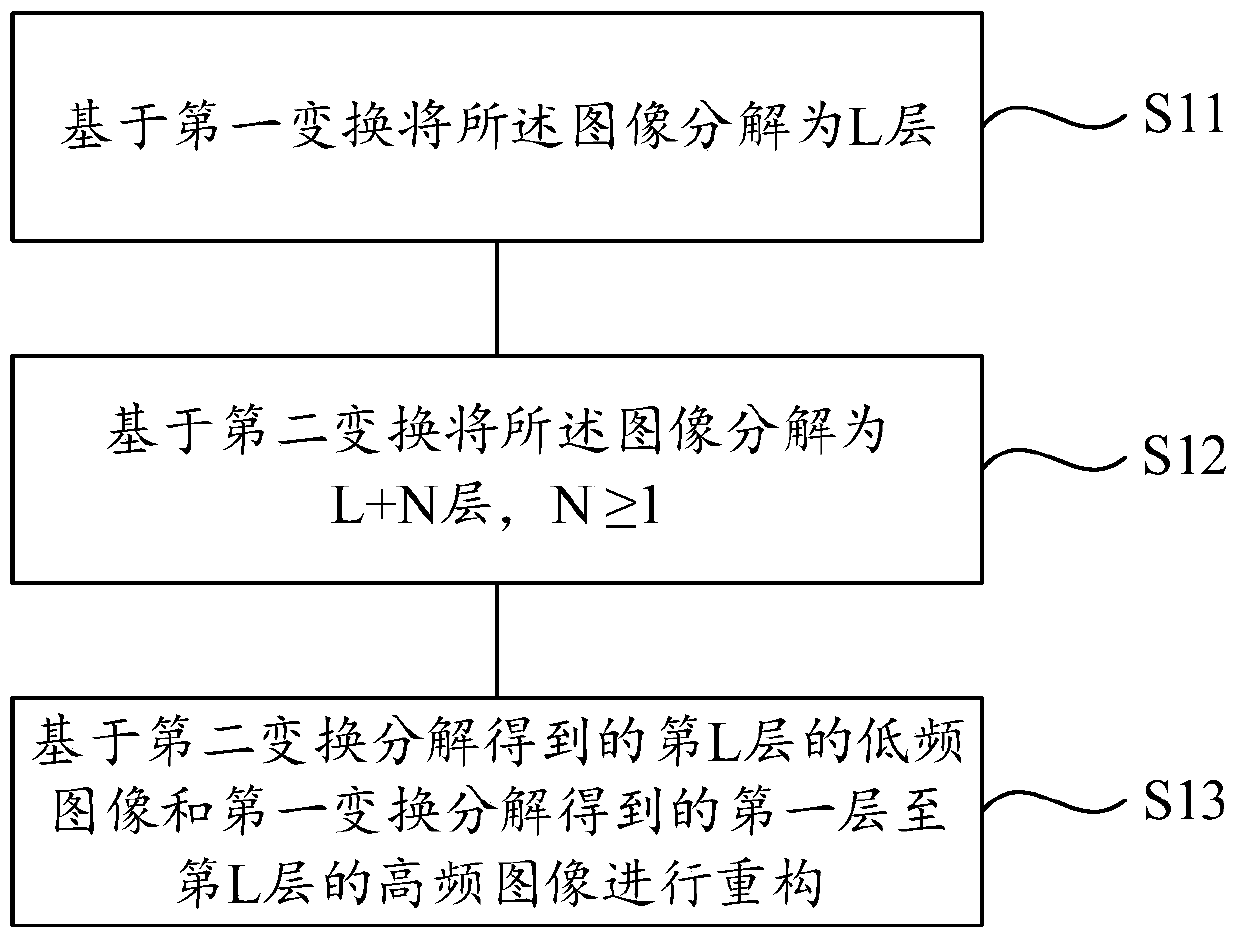
[0051] Perform S11: Pyramid decomposition of the image is performed through Laplace transform to obtain high-frequency images and low-frequency images of each layer of the image. For example, if the image is decomposed into three layers using the Laplace transform, the image is first decomposed into the low-frequency image of the first layer and the high-frequency image of the first layer, and then the first layer The low-frequency image is decomposed into the low-frequency image of the second layer and the high-frequency image of the second layer, and then the low-frequency image of the second layer is decomposed into the low-frequency image of the third layer and the high-frequency image of the third layer. In this embodiment, the image is decomposed into several layers through the Laplace transform, which can be determined according to the actual size of the image and the actual needs in the processing process. Generally speaking, the Laplace transform is used for the image. ...
Embodiment 2
[0063] In this embodiment, the image is decomposed into L layers (the first layer to the Lth layer) by Laplace transform, and the image is decomposed into L+N layers (the first layer to the Lth layer) by wavelet transform. N layer), similar to that in the first embodiment, and will not be repeated here. The difference between this embodiment and the first embodiment is that when reconstructing the high-frequency image from the first layer to the L-th layer decomposed by the Laplace transform and the low-frequency image from the Lth layer decomposed by the wavelet transform, In order to further enhance the contrast of the reconstructed image, in this embodiment, the high-frequency images from the first layer to the Lth layer obtained by the decomposition of the Laplace transform are respectively enhanced. Specifically, the first layer to the Lth layer can be separately enhanced. The high-frequency image of the L-th layer is linearly enhanced or nonlinearly enhanced. The update ...
Embodiment 3
[0066] In this embodiment, the image is decomposed into L layers (the first layer to the Lth layer) by Laplace transform, and the image is decomposed into L+N layers (the first layer to the Lth layer) by wavelet transform. N layer), the low-frequency image of the L-th layer obtained by the wavelet transform decomposition is used to update the low-frequency image of the L-th layer obtained by the Laplace transform decomposition, and the updated low-frequency image of the Lth layer is used to sequentially compare the L-1 to The corresponding update of the low-frequency image of the first layer is similar to that in the first embodiment, and will not be repeated here. The difference between this embodiment and Embodiment 1 and Embodiment 2 is that in this embodiment, it is considered that when the images of each layer obtained by wavelet transform and Laplace transform decomposition are reconstructed, there will be oscillation artifacts. The quality of the image is affected. There...
PUM
 Abstract
Description
Claims
Application Information
 - R&D
- Intellectual Property
- Life Sciences
- Materials
- Tech Scout
- Unparalleled Data Quality
- Higher Quality Content
- 60% Fewer Hallucinations
Browse by: Latest US Patents, China's latest patents, Technical Efficacy Thesaurus, Application Domain, Technology Topic, Popular Technical Reports.
© 2025 PatSnap. All rights reserved.Legal|Privacy policy|Modern Slavery Act Transparency Statement|Sitemap|About US| Contact US: help@patsnap.com


