
Special outdoor thermal insulation electrical equipment

An electric power equipment and outdoor technology, applied in the direction of mechanical equipment, circuits, electrical components, etc., can solve problems such as transformer oil leakage, affecting normal power transmission, oil pillow hot oil splashing, etc.

Inactive Publication Date: 2016-11-16
国网山东省电力公司鱼台县供电公司 +1
View PDF6 Cites 7 Cited by
  • Summary
  • Abstract
  • Description
  • Claims
  • Application Information

AI Technical Summary

Problems solved by technology

[0005] First, outdoor transformers are prone to transformer oil leakage due to their long-term exposure to the open air; oil leakage in a single transformer will inevitably lead to a sharp reduction in its own service life, which will eventually affect the normal transmission of power
[0006] Second, outdoor transformers in summer are exposed to the scorching sun for a long time, which not only easily causes damage to the transformer, but also reduces the normal heat dissipation of the transformer oil.
[0007] Third, once the outdoor transformer oil conservator in the prior art explodes, the hot oil in the oil conservator will splash everywhere, which can easily cause surrounding fires
[0008] In addition, outdoor transformers are usually equipped with outdoor power distribution cabinets, and outdoor power distribution cabinets are exposed to sunlight for a long time, causing the internal temperature to be too high, which affects the normal use of internal power components.

Method used


Image

  • Special outdoor thermal insulation electrical equipment
  • Special outdoor thermal insulation electrical equipment
  • Special outdoor thermal insulation electrical equipment

Examples


Embodiment Construction

[0078] The present invention will be described in detail below with reference to the accompanying drawings and specific embodiments. The following embodiments are explanations of the present invention, but the present invention is not limited to the following embodiments.

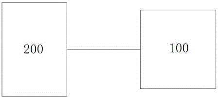
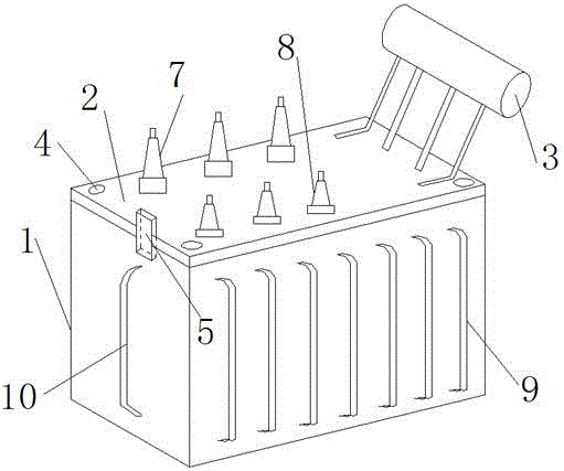
[0079] Such as Figure 1-18 As shown, the present invention provides a kind of heat-insulated power equipment dedicated to outdoors, including a transformer 100 and a power distribution cabinet 200 matched therewith. The transformer 100 includes a transformer box 1, a transformer box cover 2, an iron core and a coil Winding, the coil winding is wrapped and wound on the iron core, the iron core and the coil winding are both arranged in the transformer box 1, the transformer box 1 is filled with transformer oil, and the transformer box cover 2 Oil conservator 3 is arranged on it;

[0080] The inner surface of the distribution cabinet 200 is provided with a heat insulation board;

[0081] The transformer box...


PUM


Abstract

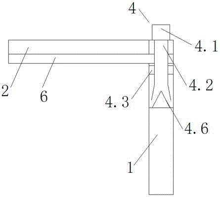
The invention relates to special outdoor thermal insulation electrical equipment. The special outdoor thermal insulation electrical equipment comprises a transformer and a power distribution cabinet, wherein the transformer comprises a transformer box body, a transformer box cover, an iron core and a coil winding; the coil winding is wound around the iron core in a wrapping manner; the iron core and the coil winding are both arranged in the transformer box body; the transformer box body is filled with transformer oil; a conservator is arranged on the transformer box cover; a thermal insulation plate is arranged on the inner surface of the cabinet body of the power distribution cabinet; the transformer box cover is fastened on the transformer box body through fastening bolts; an alarm protection structure is arranged between the transformer box cover and the transformer box body; a sealing rubber mat is also arranged between the transformer box cover and the transformer box body; high-voltage wire-outlet sleeve pipes and low-voltage wire-outlet sleeve pipes are also arranged on the transformer box cover; main radiating pipes are arranged on the front and back sides of the transformer box body; auxiliary radiating structures are arranged on the left and right sides of the transformer box body; an anti-theft oil drain valve is arranged at the bottom of the transformer box body; and the transformer also comprises a high-voltage wiring structure, a low-voltage wiring structure and a wire-breaking detection apparatus.

Description

technical field [0001] The invention belongs to the technical field of power systems, and relates to heat-insulating power equipment specially used for outdoors. Background technique [0002] As a kind of power equipment used in the power system, the transformer is an indispensable element in the entire power grid transmission process, and plays a decisive role in the normal operation of the power grid. [0003] With the continuous progress of economic development, power grid construction is spread all over the country; more and more outdoor transformers are installed due to the needs of power grid construction. [0004] Although the installation of outdoor transformers can reduce the cost of grid construction and effectively improve the transmission performance of the grid; however, outdoor transformers are prone to the following problems due to their long-term exposure to the open air: [0005] First, outdoor transformers are very prone to transformer oil leakage due to t...

Claims


Application Information

Patent Timeline
Patent Type & Authority Applications(China)
IPC IPC(8): H01F27/14F16B41/00F16B23/00C08L83/04C08L91/06C08K13/04C08K7/14C08K5/09C08K3/34C08K3/04
CPCC08L83/04C08L91/06C08L2205/02C08L2205/025C08L2205/035F16B23/0023F16B41/005H01F27/14H01F27/18H01F27/325C08K13/04C08K7/14C08K5/09C08K3/346C08K3/04
Inventor 张伟苗强田东赵树森吴振
Owner 国网山东省电力公司鱼台县供电公司
Learn More