Clamp assembly of amorphous alloy transformer body and amorphous alloy transformer

An amorphous alloy and transformer technology, applied in the field of transformers, can solve problems such as coils that cannot provide sufficient extrusion force, fail to meet national standards, and poor clamping effect, and achieve large clamping force, small reactance change range, and good effect Effect

Active Publication Date: 2016-11-16
宁波新胜中压电器有限公司
View PDF7 Cites 2 Cited by
  • Summary
  • Abstract
  • Description
  • Claims
  • Application Information

AI Technical Summary

Problems solved by technology

[0005] The disadvantages of the prior art are: 1. Under the action of fasteners, the closing ranges of the upper end of the frame and the upper end of the frame are inconsistent, causing the transformer body to tighten up and down when clamping, and the clamping effect is poor; 2. The transformer body The coil relies on the extrusion force of the iron core to prevent the coil from bending outward, but because the position and shape of the iron core are relatively fixed and cannot withstand large forces, it cannot provide enough extrusion force to resist the coil deformation, and the reactance increases , resulting in failure to meet national standards

Method used


Image

  • Clamp assembly of amorphous alloy transformer body and amorphous alloy transformer
  • Clamp assembly of amorphous alloy transformer body and amorphous alloy transformer
  • Clamp assembly of amorphous alloy transformer body and amorphous alloy transformer

Examples


Embodiment Construction

[0021] The present invention will be further described in detail below in conjunction with the accompanying drawings and embodiments.

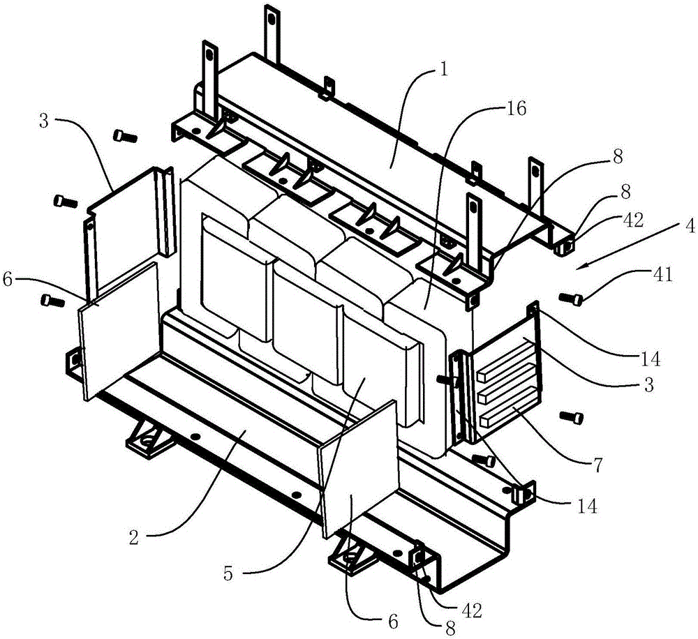
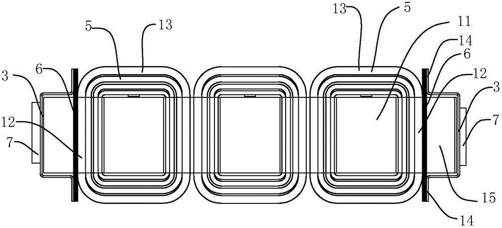
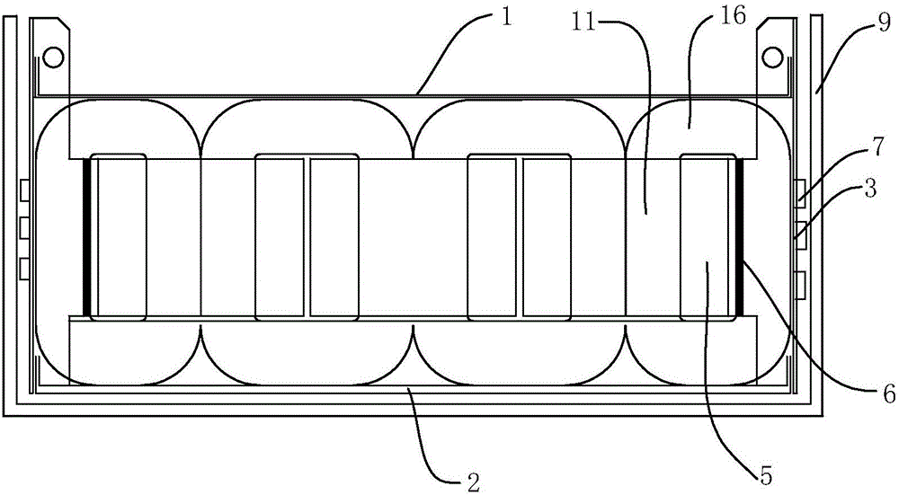
[0022] Such as Figure 1-Figure 3 As shown, the clamp assembly of the amorphous alloy transformer body includes an upper fixing frame 1 and a lower fixing frame 2 for fixing the transformer body 11, and a tightening assembly is arranged between the upper fixing frame 1 and the lower fixing frame 2, The tightening assembly includes two independent side clamping plates 3 and a displacement adjustment component 4 for moving and fixing the side clamping plates 3 to the inside. The side clamping plates 3 are provided with a support portion 14, and the inner side of the side clamping plates 3 is provided with a socket for inserting a transformer. The insulation reinforcing plate 6 between the iron core 16 of the body 11 and the coil 5; when the side splint 3 moves inward as a whole under the action of the displacement adjustment assembly 5, the supp...


PUM


Abstract

The invention discloses a clamp assembly of an amorphous alloy transformer body and an amorphous alloy transformer. The clamp assembly of the amorphous alloy transformer body comprises an upper fixing frame and a lower fixing frame for fixing the transformer body, wherein a fastening assembly is arranged between the upper fixing frame and the lower fixing frame and comprises two independent lateral clamping plates and a displacement adjusting assembly; each lateral clamping plate is provided with a support part; an insulating reinforcing plate is arranged at the inner side of each lateral clamping plate; and when the lateral clamping plates integrally move towards the inner sides under the action of the displacement adjusting assembly, the support parts are pressed against the corresponding insulating reinforcing plates and propelled towards the inner sides. The clamp assembly has the advantages that the two lateral clamping plates are arranged independently of the upper fixing frame and the lower fixing frame and move towards the inner sides under the action of the displacement adjusting assembly; and the insulating reinforcing plates are pushed through the support parts to be tightly attached to a coil of the transformer body, so that the clamping fixing effect on the transformer body is relatively good; outward bending deformation of the coil of the transformer is prevented; and the reactance change range is small.

Description

technical field [0001] The invention relates to the field of transformers, in particular to a clamp component of an amorphous alloy transformer body and an amorphous alloy transformer. Background technique [0002] The transformer includes a shell and a transformer body. The transformer body is composed of an iron core (or magnetic core) and a coil. The coil has two or more windings. According to the form of iron core, transformers are divided into: core type transformer, amorphous alloy transformer and shell type transformer. Among them, the amorphous alloy transformer refers to a new type of magnetic material, and the no-load current drops by about 80%. It is a distribution transformer with an ideal energy-saving effect, and is especially suitable for rural power grids and developing areas where the load rate is low. [0003] Limited by the amorphous alloy strip, the amorphous alloy transformer winding is generally a rectangular structure. This winding structure has poor ...

Claims


Application Information

Patent Timeline
Patent Type & Authority Applications(China)
IPC IPC(8): H01F27/30H01F27/00
CPCH01F27/00H01F27/306
Inventor 姜建松应肖磊
Owner 宁波新胜中压电器有限公司
Why Eureka
Try Eureka