Probe

The technology of a probe and a probe seat is applied to a probe. It can solve problems such as waste of human resources, fire, unstable and safe use, and achieve the effect of solving heating problems

Active Publication Date: 2016-11-16
DONGGUAN YINGZHIBAO ELECTRONICS TECH
View PDF6 Cites 11 Cited by
  • Summary
  • Abstract
  • Description
  • Claims
  • Application Information

AI Technical Summary

Problems solved by technology

[0003] 1) It takes a long time to lock the screw, which directly leads to a large waste of human resources;
[0004] 2) There are hidden problems such as quality and safety in manual operation;
[0005] 3) The lock screw process has great restrictions on the structure of the cell structure, which makes the design of the cell very limited. Some designs need to add several post-processes in the production process to complete, which is a waste of materials and human resources. It also limits the diversification of product structure;
[0006] 4) It is not easy to achieve mass production
However, in the past few years, the high-current probes produced on the market have always had safety problems of unstable use, including developed countries such as Japan and South Korea, because the contact part of the probe cannot fully contact the tab of the battery core. The contact will lead to high temperature and burn out the probe and the tab, and sometimes there will be a fire phenomenon.
[0008] At present, in the processing technology of the probe, the end face of the probe can be processed very flat, and the tab of the battery cell is also relatively flat, but both workpieces are movable, and there will always be a certain deflection during production , in many cases, the deflection angle is invisible to the naked eye, so two parts that seem to be in good contact will be found to have only a few effective contact points after zooming in, which will increase the contact surface resistance of conduction. The temperature rises, and finally burns out the battery cell

Method used


Image

  • Probe
  • Probe
  • Probe

Examples


Embodiment Construction

[0023] The present invention will be described in further detail below in conjunction with the specific embodiments and the accompanying drawings, but the embodiments of the present invention are not limited thereto.

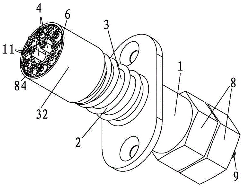
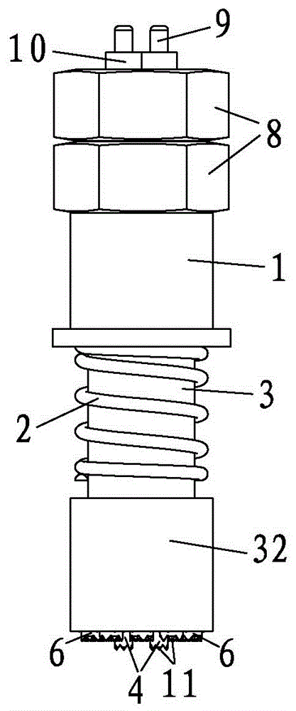
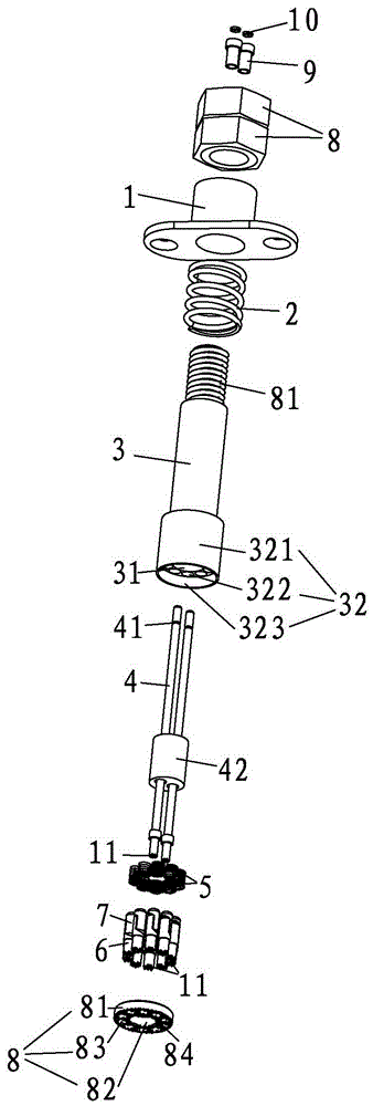
[0024] like Figure 1~4 As shown, a probe includes a probe base 1, a first spring 2, a current needle bar 3, a voltage needle 4, a second spring 5, a current needle head 6, an expansion head 7 and a probe end cover 8, the first The spring 2 and the probe base 1 are sequentially set on the current needle bar 3. The material of the probe base 1 is made of PBT plus fiber, so that it can work normally at a temperature within 120 degrees. The current needle bar 3 is set as a hollow cavity 31, and the current The needle bar 3 is made of brass, and the relative force between it and the probe base 1 is generated by the first external spring 2. One end of the voltage needle 4 passes through the hollow cavity 31 and protrudes from the current needle bar 3, and the current...


PUM


Abstract

The invention belongs to the technical field of batteries, and especially relates to a probe. The probe comprises a probe base, a first spring, a current probe rod, a voltage probe, a second spring, a current probe, an expansion head, and a probe end cover. The first spring and the probe seat are sequentially disposed on the current probe rod in a sleeving manner. The current probe rod is provided with a hollow cavity. One end of the voltage probe passes through the hollow cavity to extend out of the current probe rod. An end part of the current probe rod is provided with an accommodation part, and the accommodation part comprises an accommodation part body, an accommodation hole, and an accommodation groove, wherein the accommodation hole and the accommodation groove are disposed on the accommodation part body. The second spring is disposed in the accommodation hole, and the current probe and the expansion head are cooperatively connected, and are inserted into the second spring. The other ends of the current probe and the voltage probe are respectively provided with a sharp tooth part. The probe cover covers the accommodation groove. The arrangement of the above structure enables the probe to solve a problem of the connection of an electrode lug and a power supply during the formation and capacity grading of large-capacity power batteries.

Description

technical field [0001] The invention belongs to the technical field of batteries, in particular to a probe. Background technique [0002] The development and application of lithium batteries only appeared in modern times, and the corresponding production equipment developed much later than other traditional industries. The mass production of power batteries has only begun in recent years. In the initial stage of production, basically 50A The above batteries are produced. In the process of forming and dividing, the connection between the power supply and the battery is completed by locking the positive and negative wire lugs of the power supply on the two tabs of the battery core through screws. Yes, using this method to mass-produce batteries has great constraints on efficiency and technology. The main factors that create this constraint are as follows: [0003] 1) It takes a long time to lock the screw, which directly leads to a large waste of human resources; [0004] 2)...

Claims


Application Information

Patent Timeline
Patent Type & Authority Applications(China)
IPC IPC(8): H01R11/18H01R11/32G01R1/067
CPCG01R1/06711H01R11/18H01R11/32H01R2201/20
Inventor 杨利雄杨龙
Owner DONGGUAN YINGZHIBAO ELECTRONICS TECH
Why Eureka
Try Eureka