Eureka AIR delivers breakthrough ideas for toughest innovation challenges, trusted by R&D personnel around the world.

Low-voltage ride-through control method for self-sealing type electromagnetic coupling speed-regulating wind generation set

A technology of low-voltage ride-through and electromagnetic coupling, applied in the direction of synchronous generator control, control system, control generator, etc., can solve problems such as limited overload capacity, damage to switchgear, difficulty in supporting grid voltage, etc., achieve fast response speed, avoid Effects of pollution and service life extension

Active Publication Date: 2016-11-16
QINGDAO UNIV
View PDF2 Cites 6 Cited by
  • Summary
  • Abstract
  • Description
  • Claims
  • Application Information

AI Technical Summary

Problems solved by technology

However, since power electronic switchgear is very sensitive to overvoltage and overcurrent, overvoltage or overcurrent may cause damage to the switchgear in a short period of time, so the overload capacity of power electronic switchgear is very limited compared with synchronous generators , which makes it difficult for the reactive power generated by doubly-fed and full-power conversion wind turbines to support the grid voltage when the grid voltage drops

Method used


Image

  • Low-voltage ride-through control method for self-sealing type electromagnetic coupling speed-regulating wind generation set
  • Low-voltage ride-through control method for self-sealing type electromagnetic coupling speed-regulating wind generation set
  • Low-voltage ride-through control method for self-sealing type electromagnetic coupling speed-regulating wind generation set

Examples


Embodiment Construction

[0037]The following will clearly and completely describe the technical solutions in the embodiments of the present invention with reference to the accompanying drawings in the embodiments of the present invention. Obviously, the described embodiments are only some, not all, embodiments of the present invention. Based on the embodiments of the present invention, all other embodiments obtained by persons of ordinary skill in the art without making creative efforts belong to the protection scope of the present invention.

[0038] Compared with the synchronous generators in conventional power plants, the current doubly-fed and full power conversion wind turbines have different grid-connected interfaces. On the surface, the grid-connected interfaces of these two types of wind turbines are no longer synchronous generators. Essentially, these two wind turbines are current-controlled power sources, while synchronous generators are voltage-controlled power sources.

[0039] The present...


PUM


Abstract

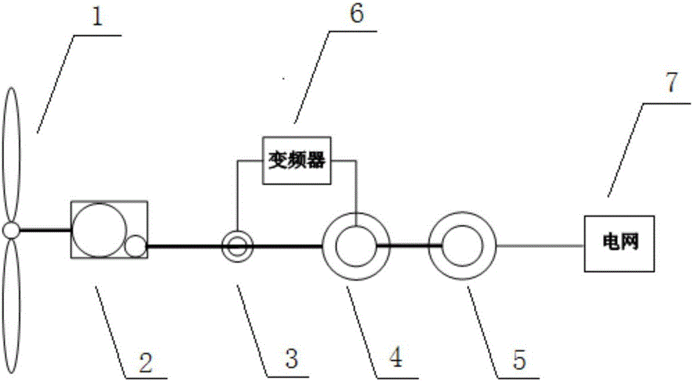
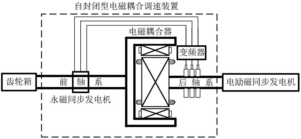
The invention provides a low-voltage ride-through control method for a self-sealing type electromagnetic coupling speed-regulating wind generation set, aiming at solving the problem that current double-feedback type and full-power conversion type wind generation sets and a synchronous power generator in a conventional power plant have different gird-connected interfaces. The invention provides the low-voltage ride-through control method for the self-sealing type electromagnetic coupling speed-regulating wind generation set. A self-sealing type electromagnetic coupling speed-regulating device is jointed with a gearbox high-speed shaft and an electrical excitation synchronous power generator rotor shaft and power is transmitted to the side of an electrical excitation synchronous power generator from the side of a gearbox; and a gird-connected interface is the electrical excitation synchronous power generator. According to the self-sealing type electromagnetic coupling speed-regulating wind generation set and the control method thereof, pollution to a power grid, which is possibly caused by the connection of a frequency converter and the power grid, is avoided, and the gird-connected interfaces of the wind generation set and the conventional power plant are the same; and a power grid friendly type target of the wind generation set is really realized and further development of wind power, namely a clean energy source, is facilitated.

Description

technical field [0001] The invention relates to the field of wind power, in particular to a control method for a self-enclosed electromagnetic coupling speed-regulating wind turbine. Background technique [0002] The current mainstream wind turbines are doubly-fed and full-power conversion wind turbines, both of which can change the speed of the wind rotor with the change of wind speed, thereby realizing the ability to capture wind energy to the maximum. However, as the proportion of wind power in the power grid increases, the demand for wind turbines to participate in supporting the voltage and frequency of the power grid continues to increase. In these two aspects, the current wind power generation unit has shortcomings compared with conventional power generation units. [0003] In terms of grid voltage support, the stator of the generator in the doubly-fed wind turbine is directly connected to the grid, and a drop in the grid voltage will cause overcurrent of the stator a...

Claims


Application Information

Patent Timeline
Patent Type & Authority Applications(China)
IPC IPC(8): H02J3/38H02J3/40H02P9/10H02P101/15H02P103/20
CPCH02J3/386H02J3/40H02P9/102H02P2101/15H02P2103/20Y02E10/76
Inventor 由蕤柴建云孙旭东
Owner QINGDAO UNIV
Why Eureka
Eureka Blog
Learn More