Power-battery-power-supply-to-electric-control-power-supply automatic emergency switching and alarm device for power buoy and control method thereof

A technology of alarm device and power electricity, which is applied in the direction of circuit device, emergency power supply arrangement, electrical components, etc., can solve the problems of power buoy loss, difficulty of power buoy, and inability to transmit position information of power buoy, so as to achieve full utilization, Fast response, to achieve the effect of continuous normal work

Active Publication Date: 2016-11-16
HARBIN ENG UNIV
View PDF4 Cites 2 Cited by
  • Summary
  • Abstract
  • Description
  • Claims
  • Application Information

AI Technical Summary

Problems solved by technology

When the power of the electric control battery pack is exhausted first, and the power battery pack has power, the main controller powered by the electric control battery pack cannot work. The position information of the dynamic buoy cannot be transmitted to the remote staff in real time through the radio, which makes it more difficult for the staff to search for the power buoy that has lost contact, and even the power buoy is lost

Method used


Image

  • Power-battery-power-supply-to-electric-control-power-supply automatic emergency switching and alarm device for power buoy and control method thereof
  • Power-battery-power-supply-to-electric-control-power-supply automatic emergency switching and alarm device for power buoy and control method thereof
  • Power-battery-power-supply-to-electric-control-power-supply automatic emergency switching and alarm device for power buoy and control method thereof

Examples


Embodiment Construction

[0020] The present invention will be further described below with examples in conjunction with the accompanying drawings.

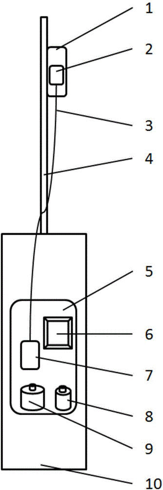
[0021] Like ordinary buoys, powered buoys can float on the water. Its antenna mast is not easy to be submerged in water. Therefore, an alarm light can be installed on the antenna mast. When the electric control battery is exhausted, the alarm light will be turned on to give an alarm.

[0022] combine figure 1 , the light alarm module 2 is installed in the waterproof light sealing cabin 1, and the waterproof light sealing cabin 1 is installed on the antenna mast 4; the power battery 9, the electric control battery 8, the power switching module 7 and other control modules 6 are all installed in the buoy main body 10 In the waterproof electronically controlled sealed cabin 5, the waterproof light sealed cabin 1 is connected to the waterproof electronically controlled sealed cabin 5 through a waterproof cable 3, more specifically, the power battery power conn...


PUM


Abstract

The invention provides a power-battery-power-supply-to-electric-control-power-supply automatic emergency switching and alarm device for a power buoy and a control method thereof. The automatic emergency switching and alarm device comprises an electric control sealed cabin and a waterproof lamp sealed cabin. The electric control sealed cabin is internally provided with a power battery, an electric control battery, a power supply switching module and a control module; the waterproof lamp sealed cabin is internally provided with a light alarm module; a power battery power connector of the power supply switching module is connected with the output end of the power battery; an electric control battery power connector of the power supply switching module is connected with the output end of the electric control battery; a power supply switching signal output end of the power supply switching module is connected with a power supply switching signal input end of the control module; and the power supply switching module is connected with the light alarm module through a waterproof cable. The device does not need an extra high-capacity stand-by power supply; and when the power battery has a large amount of residual electric quantity, an electronic device is automatically switched to the power battery for power when the electric control battery is in the undervoltage state, thereby realizing uninterrupted work and automatic alarm of the electronic device.

Description

technical field [0001] The invention relates to a device for automatic emergency conversion of the power supply of a powered buoy to electronically controlled power supply. The invention also relates to a control method for automatic emergency conversion of the power supply of the power buoy to electronically controlled power supply. Background technique [0002] A dynamic buoy is a buoy that does not need to be anchored and fixed, and can move autonomously and stay at a fixed point. Compared with mooring buoys, dynamic buoys have larger and more complex electrical equipment, and consume more power. Therefore, dynamic buoys need a more stable power supply to ensure the normal operation of electrical equipment. Because the mooring buoy is fixed, it will not flow with the current; while the power buoy that is out of control will flow with the current, making it difficult for the staff to find the power buoy that has lost contact. Therefore, it is necessary to provide and des...

Claims


Application Information

Patent Timeline
Patent Type & Authority Applications(China)
IPC IPC(8): H02J9/06
CPCH02J9/061
Inventor 管凤旭刘怀东严浙平张宏瀚周佳加车浩周丽萍
Owner HARBIN ENG UNIV
Why Eureka
Try Eureka