
An electromagnetic compatibility chassis

A compatible machine and electromagnetic technology, applied in the direction of chassis/cabinet/drawer parts, screening chassis, electrical components, etc., can solve the problems of large size, limited functional application, combined use, etc., to achieve small size, avoid Adverse effects, easy installation effect

Active Publication Date: 2022-01-04
CHONGQING DAJI ELECTRONICS TECH
View PDF0 Cites 0 Cited by
  • Summary
  • Abstract
  • Description
  • Claims
  • Application Information

AI Technical Summary

Problems solved by technology

[0002] With the development of science and technology, the number and types of modern electronic, electrical and information equipment are increasing, and there are more and more various electromagnetic interferences, and the requirements for electromagnetic compatibility in various aspects such as production, testing and use are increasing. At present, the problem of shielding magnetic field and filtering is mainly solved by the electromagnetic compatibility chassis at the same time; the usual electromagnetic compatibility chassis cannot be installed on the external support structure or device for combined use due to its simple structure design, which limits the use of the electromagnetic compatibility chassis to a certain extent. functional application; while the structure design of the traditional electromagnetic compatibility chassis is unreasonable, the electromagnetic shielding box and the filter module include independent shielding shells, which are large in size and heavy in weight, and are not easy to be installed and used in combination with other external support structures; for the electromagnetic compatibility of the chassis In some cases, because the filter module of the EMC chassis or the input docking device of the filter module is not fool-proofed at the terminal, reverse connection may occur during use; and the existing EMC chassis does not have anti-fooling Reverse connection function, and the common anti-reverse connection scheme used in other fields is reverse connection disconnection without output, this state sometimes does not attract the attention of the operators in time and may even cause troubles to the operators; in addition, in actual use, it will be necessary Add interference to the signal to detect the actual feedback of the back-end products. When the fault state signal output cannot be simulated by the front-end equipment, it needs to be added by an external device, thus increasing the equipment demand. Therefore, it is necessary to design a new electromagnetic compatibility chassis be resolved

Method used


Image

  • An electromagnetic compatibility chassis
  • An electromagnetic compatibility chassis
  • An electromagnetic compatibility chassis

Examples


Embodiment Construction

[0023] The technical solutions in the present invention will be further described below in conjunction with the accompanying drawings and embodiments.

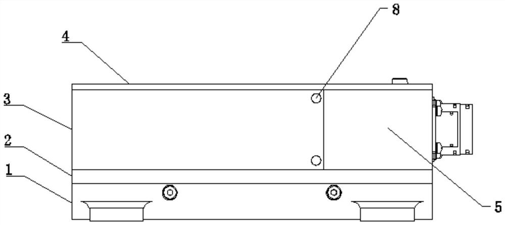
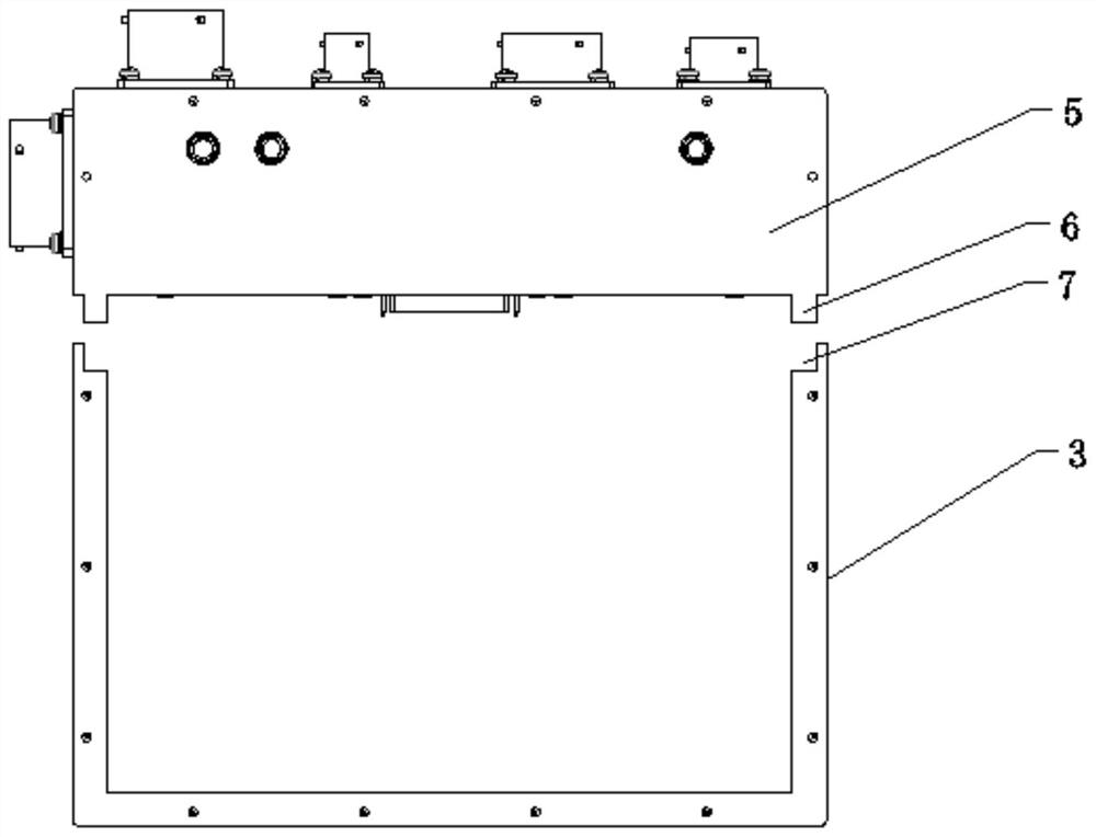
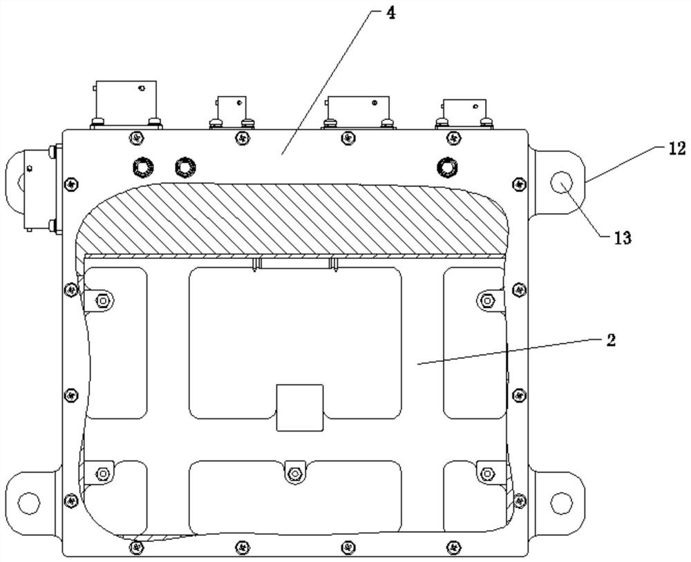
[0024] An electromagnetic compatibility case, including a shielding box body and a filter module, the filter module includes a shielding case, a filter circuit, and an input connector and an output connector installed on the shielding case and respectively connected to the input end and output end of the filter circuit correspondingly, the shape of the shielding case It is generally a rectangular parallelepiped structure, and the filter circuit includes an anti-reverse connection unit; figure 1 As shown, the shielding box includes a fixing plate 1, a shielding bottom plate 2, a shielding main body box 3 and a shielding cover plate 4, and the fixing plate 1 is used to fix and install the electromagnetic compatibility chassis on the external support structure; the shielding main body box 3. The cross-section is "凵" shape, and it...


PUM


Abstract

The invention provides an electromagnetic compatibility case, which includes a shielding box body and a filtering module. The filtering module includes a shielding shell, a filtering circuit, and an input joint and an output joint installed on the shielding shell and respectively connected to the input end and the output end of the filtering circuit correspondingly. The shape of the shielding shell is generally a cuboid structure, and the filter circuit includes an anti-reverse connection unit; the shielding box body includes a fixing plate, a shielding bottom plate, a shielding main body box and a shielding cover plate, and the fixing plate is used to fix the electromagnetic compatibility chassis on the outside On the supporting structure: the fixed plate, the shielding bottom plate, the shielding main body box and the shielding cover plate are fixedly connected in sequence from bottom to top, and together with the shielding shell of the filter module form a sealed box that shields external electromagnetic waves. The beneficial effect of the present invention is that the case is small in size, convenient to install, and suitable for more use environments.

Description

technical field [0001] The invention relates to the field of electronic equipment, in particular to an electromagnetic compatibility case. Background technique [0002] With the development of science and technology, the number and types of modern electronic, electrical and information equipment are increasing, and there are more and more various electromagnetic interferences, and the requirements for electromagnetic compatibility in various aspects such as production, testing and use are increasing. At present, the problem of shielding magnetic field and filtering is mainly solved by the electromagnetic compatibility chassis at the same time; the usual electromagnetic compatibility chassis cannot be installed on the external support structure or device for combined use due to its simple structure design, which limits the use of the electromagnetic compatibility chassis to a certain extent. functional application; while the structure design of the traditional electromagnetic...

Claims


Application Information

Patent Timeline
Patent Type & Authority Patents(China)
IPC IPC(8): H05K5/02H05K9/00
CPCH05K5/0204H05K5/0217H05K5/0247H05K9/0007H05K9/0016
Inventor 耿利群何天成董俊峰黄记堂肖瑶
Owner CHONGQING DAJI ELECTRONICS TECH
Learn More