Self-piercing rivet

A rivet, self-piercing technology, applied in the direction of rivets, screws, connecting components, etc., can solve the problem that self-piercing rivets are not satisfactory

Inactive Publication Date: 2016-11-16
BOLLHOFF VERBINDUNGSTECHNIK GMBH
View PDF15 Cites 5 Cited by
  • Summary
  • Abstract
  • Description
  • Claims
  • Application Information

AI Technical Summary

Problems solved by technology

But self-piercing rivets do not achieve satisfactory results when joint conn

Method used


Image

  • Self-piercing rivet

Examples


Embodiment Construction

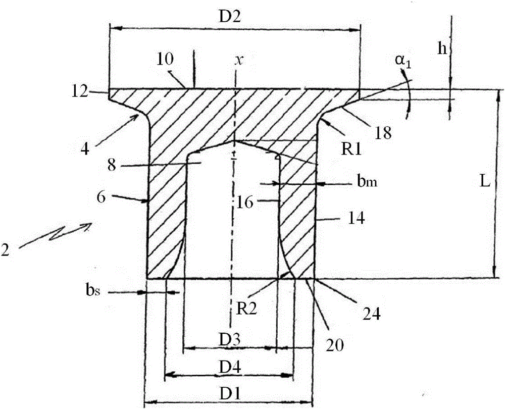
[0019] The specific embodiment of the semi-hollow self-piercing rivet of the present invention will be described with reference to the accompanying drawings. In particular, the self-piercing rivet is suitable for establishing a bonded connection between at least a first component made of high-strength steel as a top layer and a further component made of thick-walled aluminum sheet or cast aluminum or die-cast aluminum material as a mold-side component. It should be understood that the preferred self-piercing rivets of the present invention may also be used to create bonded connections in other materials.

[0020] The self-piercing rivet 2 is composed of a rivet head 4 and a rivet shaft 6, forming a rotational symmetry around the central axis X. The self-piercing rivet 2 may also preferably not form rotational symmetry with respect to the central axis X. At this time, the self-piercing rivet 2 transverse to the central axis X is preferably an ellipse or an oval. The rivet shan...


PUM


Abstract

The invention relates to a self-piercing rivet 2 for producing a joint between at least two components, which self-piercing rivet comprising a rivet head 4 and a rivet shank 6 having a central borehole 8 of the shank, said rivet shank 6 also having a cylindrical outer surface 14 of the shank and an inner surface 16 of the shank bordering the central borehole 8 of the shank, while the outer surface 14 of the shank and the inner surface 16 of the shank are connected to the axial end of the rivet shank 6 facing away from the rivet head 4 via a flat bottom surface 20 of the shank and a shank end radius R2, said shank end radius R2 tangentially transitioning into the inner surface 16 of the shank, and said flat bottom surface 20 of the shank being connected to the outer surface 14 of the shank via a cutting edge 24.

Description

technical field [0001] The present invention relates to a self-piercing rivet, in particular a semi-hollow self-piercing rivet for producing a bonded connection in at least two components, especially suitable for components made of high-strength steel and thick-walled aluminum plates or cast aluminum Create bonded connections between components. Background technique [0002] As a connection method, stamping riveting has been widely used in industry. Especially in automobile manufacturing, new requirements always fall on the connection of stamping rivets. This is mainly because, depending on the material to be combined, such as steel, high-strength steel, magnesium alloy sheet, plastic, carbon fiber reinforced plastic (CFRP, carbon fiber reinforced plastic) and similar materials, the task of joining these materials must be solved again and again. In addition, combined with the shortening of the production cycle for joining, the accessibility of the components to be joined a...

Claims


Application Information

Patent Timeline
IPC IPC(8): F16B19/08F16B5/04
CPCB21J15/025F16B5/04F16B19/086
Inventor 马蒂亚斯·黑格尔
Owner BOLLHOFF VERBINDUNGSTECHNIK GMBH
Why Eureka
Try Eureka