A bonding and crimping flexible tooling for aerospace power transformers
A technology for aerospace power supplies and transformers, applied in clamping, positioning devices, manufacturing tools, etc., can solve the problems of low qualification rate of pressing and fixing, and achieve the effects of simple operation, reduced production error rate, and strong practicability.
- Summary
- Abstract
- Description
- Claims
- Application Information
AI Technical Summary
Problems solved by technology
Method used
Image
Examples
Embodiment 1
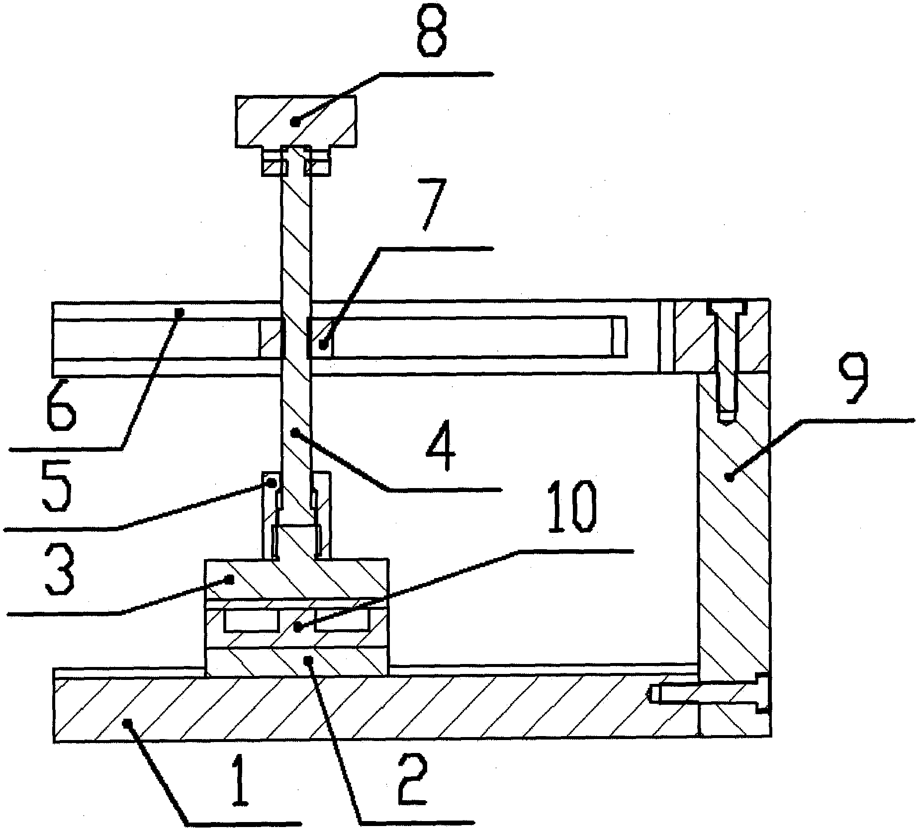
[0022] A bonding and crimping flexible tooling for an aerospace power transformer, which compacts a transformer magnetic core 10 with a layer of glue; it includes a bottom plate 1, a cushion block 2, a pressing block 3, a screw rod 4, a locking member 5, and an upper plate 6. The slider 7, the handle 8 and the column 9; the bottom plate 1 is a cuboid with a boss, and the end surface of the bottom plate 1 has threaded holes; the spacer 2 is a cuboid with a boss, and the spacer 2 is placed on the bottom plate 1 , the boss on the bottom plate 1 limits the pad 2; the pressure block 3 is a cuboid with a stud, and the stud is located at the center of the upper surface of the pressure block 3; the lower surface of the pressure block 3 is facing the pad 2 On the upper surface, a transformer magnetic core 10 is placed between the pressure block 3 and the pad 2; the boss on the pad 2 limits the position of the transformer magnetic core 10; the upper plate 6 is a cuboid with a U-shaped gr...
Embodiment 2
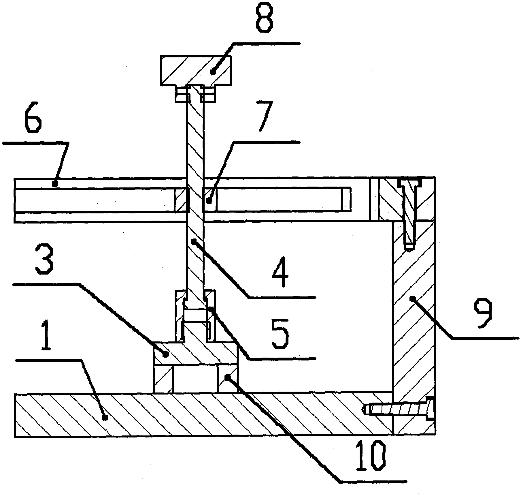
[0026] An aerospace power transformer bonding and crimping flexible tooling, the tooling is used to compact the transformer magnetic core with a layer of glue; Block 7, handle 8 and column 9; Base plate 1 is a cuboid, and the end face of base plate 1 has threaded holes; Press block 3 is a cylinder with studs, and the studs are located at the center of the upper surface of press block 3; Press block 3 The lower surface of the lower surface is facing the upper surface of the bottom plate 1, and the transformer magnetic core 10 is placed between the pressure block 3 and the bottom plate 1; 6, the slider 7 can slide horizontally in the U-shaped groove of the upper plate 6; the screw 4 passes through the U-shaped groove of the upper plate 6, that is, one end of the screw 4 is located on the upper plate 6, and the other end is located Below the plate 6, the end of the screw 4 located above the upper plate 6 is threadedly connected with the handle 8; the end of the screw 4 located be...
PUM
 Abstract
Description
Claims
Application Information
 - R&D
- Intellectual Property
- Life Sciences
- Materials
- Tech Scout
- Unparalleled Data Quality
- Higher Quality Content
- 60% Fewer Hallucinations
Browse by: Latest US Patents, China's latest patents, Technical Efficacy Thesaurus, Application Domain, Technology Topic, Popular Technical Reports.
© 2025 PatSnap. All rights reserved.Legal|Privacy policy|Modern Slavery Act Transparency Statement|Sitemap|About US| Contact US: help@patsnap.com


