
Novel rotor drum granulator

A rotary drum granulator and a new type of technology, applied in the direction of granulation in a rotary tank, can solve the problems of inconvenient installation, low output, easy accumulation of raw materials, etc., and achieve the effect of reasonable structure design and improved production efficiency.

Inactive Publication Date: 2016-11-23
宁波市镇海诚尚电气设备有限公司
View PDF1 Cites 0 Cited by
  • Summary
  • Abstract
  • Description
  • Claims
  • Application Information

AI Technical Summary

Problems solved by technology

[0003] The existing drum granulators on the market have the disadvantages of complex structure, inconvenient installation, low pelleting rate, and low particle strength, and often the output is not high; in the prior art, the drum of the drum granulator In the actual production process, there are often problems that raw materials are easy to accumulate and stick. For example, a drum granulator disclosed in Patent No. ZL201320397469.4, in the attached drawing of the drum granulator, the feed port Although the pipe is inclined to facilitate feeding, it will still cause material to accumulate at the feeding end of the pipe, thereby affecting production

Method used


Image

  • Novel rotor drum granulator
  • Novel rotor drum granulator
  • Novel rotor drum granulator

Examples


specific Embodiment 1

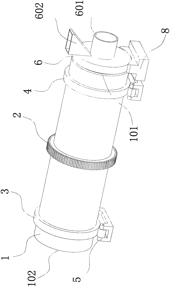
[0020] refer to figure 1 and Figure 4 , a new drum granulator, including a horizontal cylinder 1, the outer wall of the horizontal cylinder 1 is provided with a driving gear 2, a first driven pulley 3 and a second driven pulley 4, the horizontal cylinder The body 1 is supported on the support pulley structure 5 through the first driven pulley 3 and the second driven pulley 4, one end of the horizontal cylinder 1 is the feeding end 101, and the other end is the discharging end 102; The feed end 101 of the horizontal cylinder 1 is provided with a circular feed end cover 6 coaxial with the horizontal cylinder 1, and the circular feed end cover 6 is connected to the A gap is provided between the inner walls of the horizontal cylinder 1; the center of the outer surface of the circular feed end cover 6 is welded with an air inlet that is coaxial with the circular feed end cover 6. cylinder 601, the outer surface of the circular feed end cap 6 is also welded with a feed cylinder 6...

specific Embodiment 2

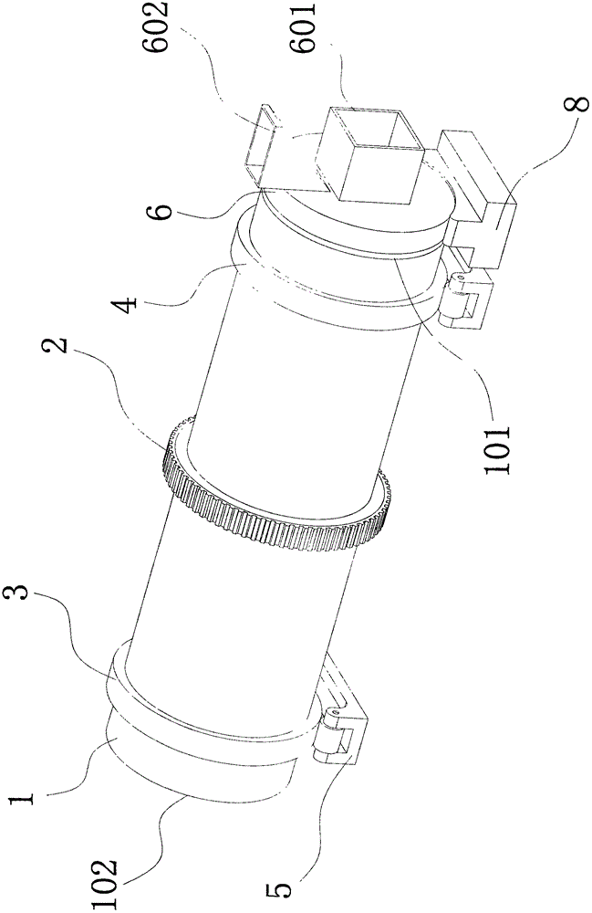
[0021] refer to figure 2 and Figure 4 , a new drum granulator, including a horizontal cylinder 1, the outer wall of the horizontal cylinder 1 is provided with a driving gear 2, a first driven pulley 3 and a second driven pulley 4, the horizontal cylinder The body 1 is supported on the support pulley structure 5 through the first driven pulley 3 and the second driven pulley 4, one end of the horizontal cylinder 1 is the feeding end 101, and the other end is the discharging end 102; The feed end 101 of the horizontal cylinder 1 is provided with a circular feed end cover 6 coaxial with the horizontal cylinder 1, and the circular feed end cover 6 is connected to the A gap is provided between the inner walls of the horizontal cylinder 1; the center of the outer surface of the circular feed end cover 6 is welded with an air inlet that is coaxial with the circular feed end cover 6. cylinder 601, the outer surface of the circular feed end cap 6 is also welded with a feed cylinder ...

specific Embodiment 3

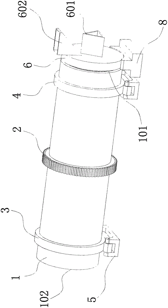
[0022] refer to image 3 and Figure 4 , a new drum granulator, including a horizontal cylinder 1, the outer wall of the horizontal cylinder 1 is provided with a driving gear 2, a first driven pulley 3 and a second driven pulley 4, the horizontal cylinder The body 1 is supported on the support pulley structure 5 through the first driven pulley 3 and the second driven pulley 4, one end of the horizontal cylinder 1 is the feeding end 101, and the other end is the discharging end 102; The feed end 101 of the horizontal cylinder 1 is provided with a circular feed end cover 6 coaxial with the horizontal cylinder 1, and the circular feed end cover 6 is connected to the A gap is provided between the inner walls of the horizontal cylinder 1; the center of the outer surface of the circular feed end cover 6 is welded with an air inlet that is coaxial with the circular feed end cover 6. cylinder 601, the outer surface of the circular feed end cap 6 is also welded with a feed cylinder 6...


PUM


Abstract

The invention relates to a granulator, specifically a new drum granulator, which includes a horizontal cylinder, and the outer wall of the horizontal cylinder is provided with a driving gear, a first driven pulley and a second driven belt The horizontal cylinder is supported on the supporting wheel structure through the first driven pulley and the second driven pulley. One end of the horizontal cylinder is the feeding end, and the other end is the discharging end; the horizontal cylinder is The feed end is provided with a circular feed end cover coaxial with the horizontal cylinder, and there is a gap between the circular feed end cover and the inner wall of the horizontal cylinder; the outer surface of the circular feed end cover The center of the circular feed end cover is welded with an air inlet tube coaxial with the center line of the circular feed end cover, and a feed tube is also welded on the outer side of the circular feed end cover. The material cylinder is located directly above the air inlet cylinder; a novel drum granulator disclosed in the present invention solves the problems existing in the prior art by setting the air inlet cylinder below the feed port.

Description

technical field [0001] The invention relates to a granulator, specifically a novel drum granulator. Background technique [0002] Drum granulator is a molding machine that can make materials into specific shapes. It is one of the key equipment in the compound fertilizer industry. It is suitable for cold and hot granulation and large-scale production of high, medium and low concentration compound fertilizers. Its main working method is granulation wet granulation, that is, through a certain amount of water or steam, the basic fertilizer is fully chemically reacted after the humidity is adjusted in the cylinder, and under certain liquid phase conditions, the rotary motion of the cylinder is used to make The extrusion force between the material particles is agglomerated into balls. [0003] The existing drum granulators on the market have the disadvantages of complex structure, inconvenient installation, low pelleting rate, and low particle strength, and often the output is no...

Claims


Application Information

Patent Timeline
Patent Type & Authority Applications(China)
IPC IPC(8): B01J2/12
CPCB01J2/12
Inventor 刘敏
Owner 宁波市镇海诚尚电气设备有限公司
Learn More