
Polishing machine rollover and limitation device

A technology of a limit device and a scanning machine, which is applied to the parts of grinding machine tools, grinding/polishing equipment, metal processing equipment, etc. Simple operation and simple structure

Inactive Publication Date: 2016-11-23
益阳强大机械制造有限公司
View PDF9 Cites 3 Cited by
  • Summary
  • Abstract
  • Description
  • Claims
  • Application Information

AI Technical Summary

Problems solved by technology

[0003] At present, due to the lack of design, the sweeping machine has defects such as troublesome operation and low sweeping efficiency.

Method used


Image

  • Polishing machine rollover and limitation device

Examples


Embodiment

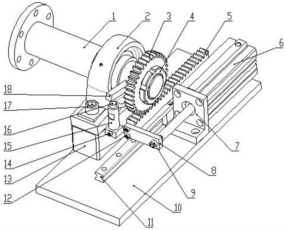
[0016] Referring to the accompanying drawings, this embodiment includes a turning shaft 1, a bearing seat 2, a turning gear 3, a turning rack 5, a cylinder 6, a cylinder seat 7, a connecting plate 8, a main mounting plate 10, a linear slide rail 11, and a bearing seat mounting seat 13. Adjusting rod 15, adjusting pad 16 and limit rod 18, the turning shaft 1 is installed on the bearing seat 2, the bearing seat 2 is fixed on the bearing seat mounting seat 13, and the bearing seat mounting seat 13 is fixed on On the main mounting plate 10, a limit rod 18 and a turning gear 3 are installed on the turning shaft 1, and the turning rack 5 is fixed on the linear slide rail 11 and meshed with the turning gear 3. The linear slide rail 11 Fixed on the main mounting plate 10, the flip rack 5 is connected to the connecting plate 8, the connecting plate 8 is connected to the cylinder 6, the cylinder 6 is fixed on the cylinder seat 7, and the cylinder seat 7 is fixed on the main installation ...


PUM


Abstract

A turning and limiting device for a sweeping machine, including a turning shaft, a bearing seat, a turning gear, a turning rack, a cylinder, a cylinder seat, a connecting plate, a main mounting plate, a linear slide rail, a bearing seat mounting seat, an adjusting rod, and an adjusting Pad and limit rod, the turning shaft is installed on the bearing seat, the bearing seat is fixed on the bearing seat mounting seat, the bearing seat mounting seat is fixed on the main mounting plate, the limit bar and the turning gear are installed on the turning shaft, and the turning rack is fixed On the linear slide rail and meshed with the flip gear, the linear slide rail is fixed on the main mounting plate, the flip rack is connected to the connection plate, the connection plate is connected to the cylinder, the cylinder is fixed on the cylinder seat, and the cylinder seat is fixed on the main installation On the board, there are two sets of adjustment rods, which are respectively located on both sides of the bearing seat mounting seat, and are adjustable threaded with the bearing seat mounting seat. The invention can effectively improve the automation degree of the light sweeping machine, improve the light sweeping efficiency, and at the same time, can effectively realize the stability of turning over of the light sweeping machine.

Description

technical field [0001] The invention relates to a turning and limiting device for a light sweeping machine. Background technique [0002] As a kind of light sweeping equipment, the flip-type single-side sweeping machine is widely used in the special-shaped surface polishing of 2.5D, 3D glass, ceramics, sapphire and other hard and brittle materials. [0003] At present, due to the lack of design, the light sweeping machine has defects such as troublesome operation and low light sweeping efficiency. Contents of the invention [0004] The technical problem to be solved by the present invention is to provide a turning and limiting device for the light sweeping machine that can effectively improve the automation of the light sweeping machine and improve the sweeping efficiency at the same time. [0005] The technical solution adopted by the present invention to solve the technical problem is: a sweeping machine turning and limiting device, including turning shaft, bearing seat...

Claims


Application Information

Patent Timeline
Patent Type & Authority Applications(China)
IPC IPC(8): B24B41/00
CPCB24B41/00
Inventor 曾永康曾启明
Owner 益阳强大机械制造有限公司
Learn More