Pipe fitting cutting clamping tool with cam

A technology for clamping tooling and cams, applied in the direction of clamping, positioning devices, manufacturing tools, etc., can solve the problems of large cutting errors of pipe fittings, vibration of pipe fittings, low production efficiency, etc., to reduce cutting errors, facilitate positioning, and save time Effect

Inactive Publication Date: 2016-11-23
CHONGQING YINGJIE SCI & TECH CO LTD
View PDF0 Cites 4 Cited by
  • Summary
  • Abstract
  • Description
  • Claims
  • Application Information

AI Technical Summary

Problems solved by technology

However, when cutting pipe fittings, a long pipe will be cut into countless small pipes of equal length at a time. If the above method is used, repositioning will be required for each cutting, which is time-consuming and laborious, and the production efficiency is low.
Another thing is that when cutting the pipe fittings, the pipe fittings will vibrate. If the pipe fittings are not clamped, it will cause a large cutting error due to the vibration of the pipe fittings.

Method used


Image

  • Pipe fitting cutting clamping tool with cam
  • Pipe fitting cutting clamping tool with cam
  • Pipe fitting cutting clamping tool with cam

Examples


Embodiment Construction

[0012] The present invention will be further described below in conjunction with the drawings and embodiments:

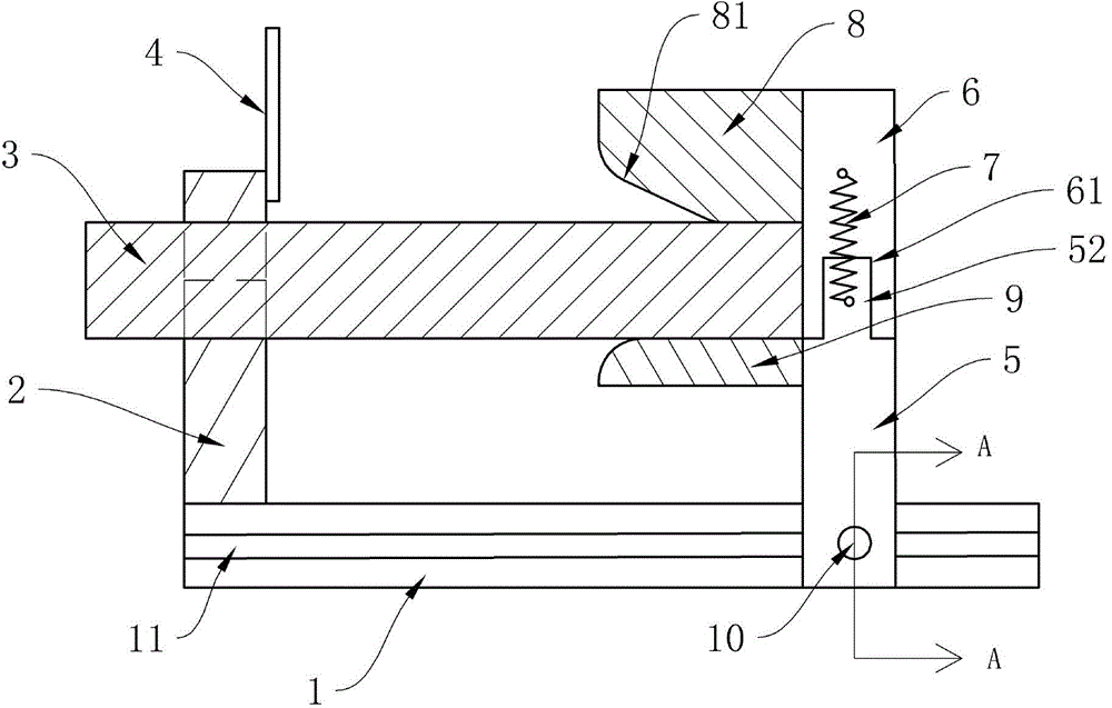
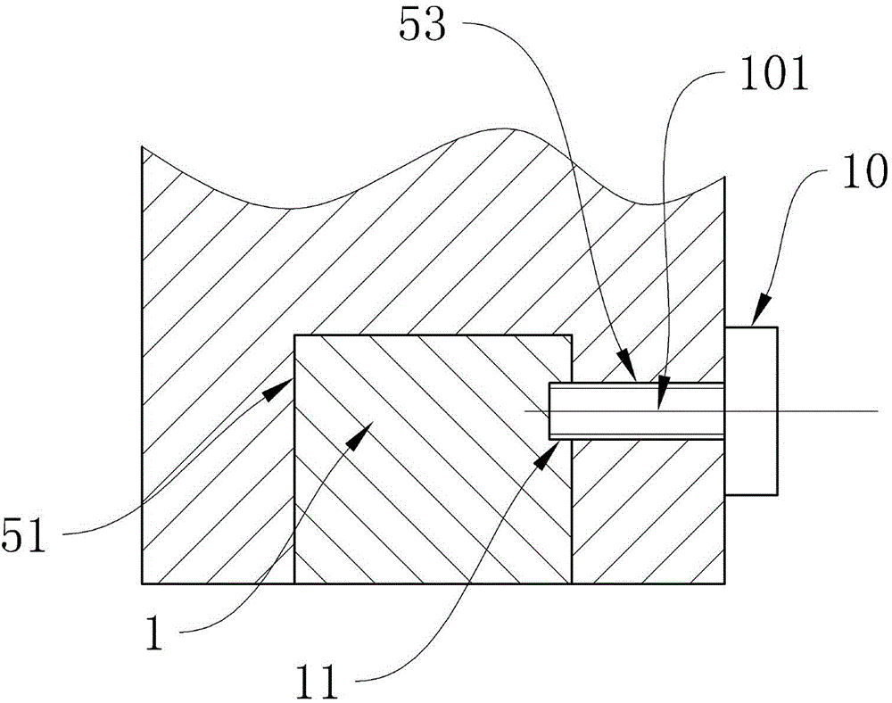
[0013] Such as Figure 1 to Figure 3 As shown, a tube cutting and clamping tool with a cam includes a limiting component and a supporting and clamping component 2. The limiting component includes a first limiting plate 5, and the bottom of the first limiting plate 5 is The end is provided with a sliding groove 51, and the sliding groove 51 is matched with the sliding rail 1; a threaded hole 53 is provided on one side of the sliding groove 51, and the bolt 10 is screwed into the threaded hole 53 and the sliding rail 1 is tightened to To make the bolt 10 better tighten the slide rail 1, a clamping groove 11 can be provided in the contact part of the slide rail 1 and the bolt 10, so that the bolt 10 can be directly clamped in the clamping groove 11;

[0014] The top of the first limiting plate 5 is provided with a stopper 9, and the stopper 9 is provided with a matching pr...


PUM


Abstract

The invention discloses a pipe fitting cutting positioning tool with a clamping function. The tool comprises a limiting part and a support clamping part. The support clamping part comprises a supporting plate fixed to a sliding rail. A semicircular mounting half groove is formed in the top of the supporting plate, and the right end of the mounting half groove is hinged to an arc-shaped gland through a first hinge. The inner side cross section of the gland is in an arc shape, and a buffer compressing block is fixed to the inner side of the gland. A pressing plate is arranged at the left end of the gland, and the lower surface of the pressing plate is connected with the top end of a stretched spring. The bottom end of the stretched spring is connected to an extending block. The center of a cam is hinged to the supporting plate through a third hinge. The top end of the cam is hinged to the right end of a first connecting rod through a fourth hinge. The left end of the first connecting rod is hinged to the top end of a second connecting rod through a fifth hinge. The bottom end of the second connecting rod is hinged to the right end of a third connecting rod through a sixth hinge. The third connecting rod is hinged to the sliding rail through a first fixed hinge. A reset spring is connected between the left end of the third connecting rod and the sliding rail.

Description

Technical field [0001] The invention relates to a positioning device, in particular to a tube cutting and clamping tool with a cam. Background technique [0002] When cutting pipe fittings, it is generally necessary to measure the parts that need to be cut, and then cut. However, in general, one long tube is cut into countless small tubes of equal length at a time when cutting pipe fittings. If the above method is adopted, a repositioning is required for each cut, which is time-consuming and labor-intensive, and the production efficiency is low. Moreover, when the pipe is cut, the pipe will vibrate. If the pipe is not clamped, it will cause a large cutting error due to the vibration. Summary of the invention [0003] In view of the above-mentioned defects of the prior art, the technical problem to be solved by the present invention is to provide a pipe cutting and positioning tool with a clamping function. [0004] In order to achieve the above objective, the present invention pro...

Claims


Application Information

Patent Timeline
Patent Type & Authority Applications(China)
IPC IPC(8): B26D7/02B23Q3/06
Inventor 王建勇
Owner CHONGQING YINGJIE SCI & TECH CO LTD
Why Eureka
Try Eureka