Process for sawing substrate strip

a substrate strip and processing technology, applied in metal sawing accessories, metal sawing apparatus, manufacturing tools, etc., can solve the problem that the cutting error resulting from the cutting of each substrate area cannot add to the peripheral substrate area, and achieve the effect of reducing the cutting error

Inactive Publication Date: 2007-01-30
ADVANCED SEMICON ENG INC
View PDF18 Cites 3 Cited by
  • Summary
  • Abstract
  • Description
  • Claims
  • Application Information

AI Technical Summary

Benefits of technology

[0006]The present invention intends to provide a substrate sawing process that saws the substrate strips in alignment with each of the substrate areas. The saw machine is mechanically moved to the substrate areas and is positioned by the alignment of each of the substrate areas for the substrate sawing process. This reduces the cutting error in such a way as to mitigate and overcome the above problem. Because the saw machine is positioned on each of the substrate areas by corresponding alignment, a cutting error resulting from cutting of each substrate area cannot add to the peripheral substrate areas.

Problems solved by technology

Because the saw machine is positioned on each of the substrate areas by corresponding alignment, a cutting error resulting from cutting of each substrate area cannot add to the peripheral substrate areas.

Method used


Image

  • Process for sawing substrate strip
  • Process for sawing substrate strip
  • Process for sawing substrate strip

Examples


first embodiment

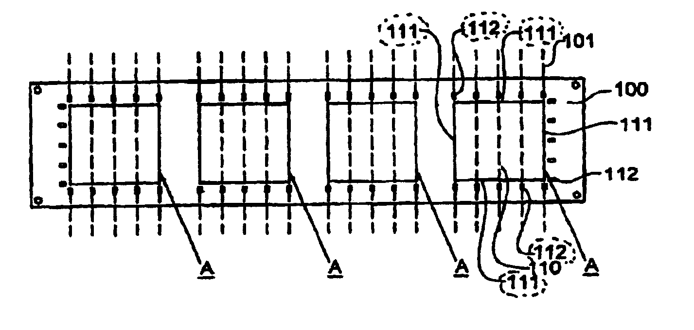
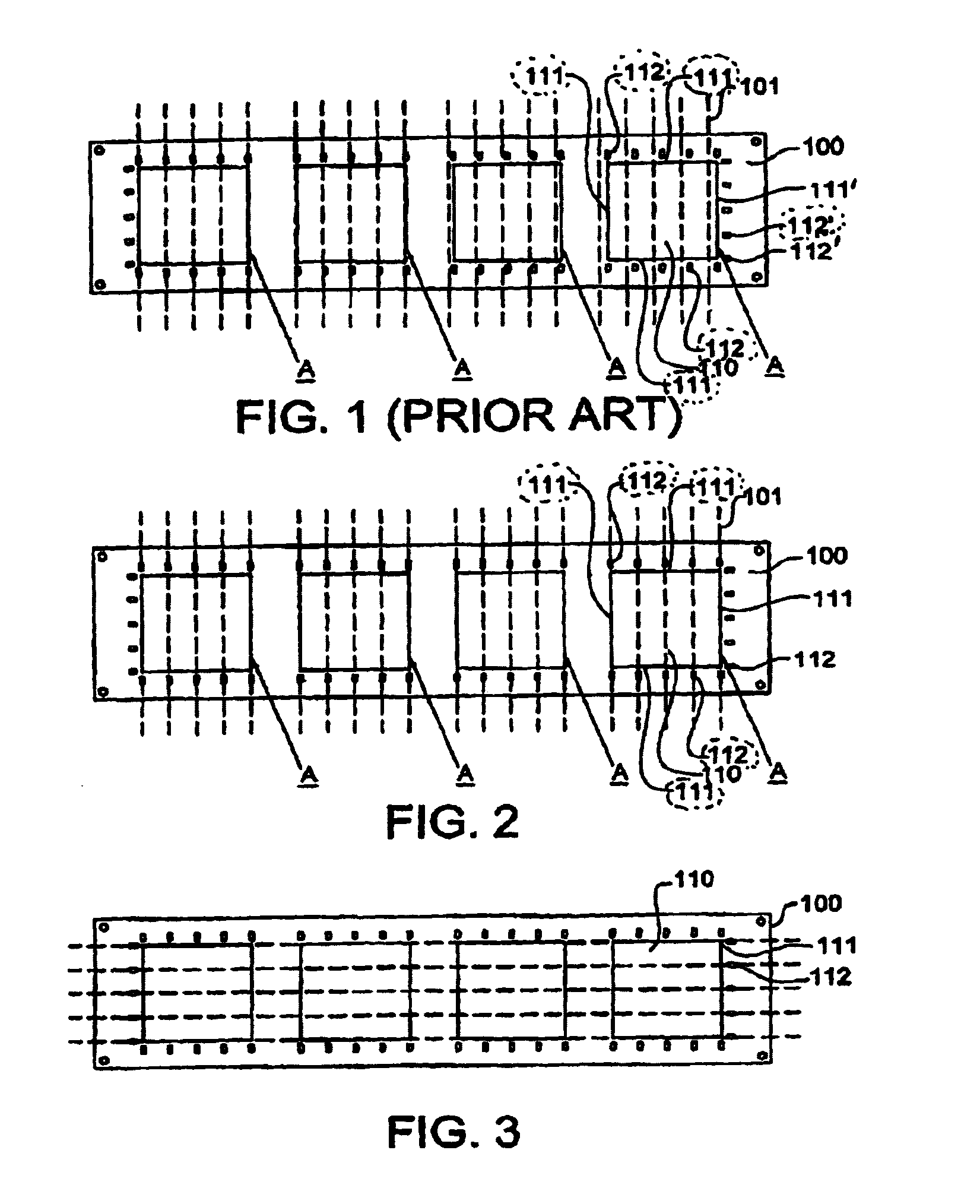
[0017]Referring to FIG. 2, according to the process for sawing substrate strip, a substrate strip 100 is placed on a plate (not shown) and is preferably suctioned to attach to the top surface of the plate through the air-holes arranged on the plate. The substrate strip 100 comprises a plurality of substrate areas 110 which are aligned in the longitudinal direction and a plurality of alignment marks 111 which are arranged around the substrate areas 110. A saw machine (not shown) is mechanically moved to the substrate areas 110 and is positioned by the alignment marks 111 of corresponding substrate areas 110. Then the saw machine measures or predetermines the cutting tracks 101 by cutting marks 112 of each substrate area 110, and then cuts the substrate areas 110 of the substrate strip 100 in the first phase. The saw machine is positioned with respect to each individual substrate area 110 according to the alignment marks 111 thereof and then the cutting tracks 101 in the first phase i...

second embodiment

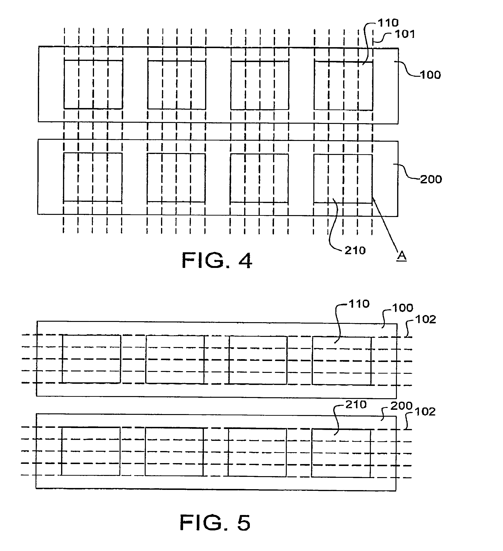
[0020]Referring to FIG. 4, according to the process for sawing substrate strip, two substrate strips 100 and 200 are juxtaposed on a plate (not shown). The substrate strips 100 and 200 have a plurality of substrate areas 110 and 210 which are adjacent to one another. The saw machine cuts the substrate strips 100 and 200 along the cutting tracks 101 in the first phase.

[0021]Referring to FIG. 5, the saw machine cuts the substrate strips 100 and 200 along the cutting tracks 102 in the second phase which is restricted in each of the substrate areas 110 and 210. The substrate strips 100 and 200 are cut along the cutting tracks 101 and the cutting tracks 102 to form the substrate of the semiconductor device. Then the saw machine find the reference point of alignment of each of the substrate strips 100 and 200 and cuts each substrate strip 100 and 200 along the predetermined cutting tracks in the first phase and the second phase.


PUM

PropertyMeasurementUnit
areasaaaaaaaaaa
areaaaaaaaaaaa
shrinkageaaaaaaaaaa

Abstract

A process for sawing a substrate strip marks corresponding to substrate areas of substrate strips which are arranged side-by-side on a plate. A saw machine is mechanically moved to the substrate areas and positioned by the alignment marks of corresponding substrate areas for cutting the substrate areas of the substrate strips in the first phase. Then the saw machine is further mechanically moved to the substrate areas again and is positioned by the alignment marks of corresponding substrate areas again for cutting the substrate areas of the substrate strips in the second phase. Therefore, an error in any of the substrate areas in the first phase and second phase will not accumulate to the subsequent substrate areas in the substrate strip.

Description

BACKGROUND OF THE INVENTION[0001]1. Field of the Invention[0002]The present invention relates generally to a substrate sawing process and more particularly to a process for sawing a substrate strip having multi-alignment means thereon.[0003]2. Description of the Related Art[0004]A conventional substrate sawing process comprises an alignment for positioning a substrate strip so as to adjust the position of a saw machine and to arrange the position of the cutting tracks for substrate sawing. As shown in FIG. 1, a substrate strip 100 comprises a plurality of substrate areas 110 which are aligned along the longitudinal direction. A plurality of alignment marks 111 enclose the substrate areas 110 for positioning a saw machine and cutting marks 112 are provided for measuring or predetermining arrangement of the cutting tracks 101 of the substrate sawing process. After the saw machine is positioned and the cutting tracks 101 are arranged, the saw machine saws the substrate strip 100 along ...

Claims


Application Information

Patent Timeline
Patent Type & Authority Patents(United States)
IPC IPC(8): B26D1/00B23D59/00H01L21/00
CPCH01L21/67092B23D59/002Y10T83/0572Y10T83/04Y10T83/531Y10T83/05Y10T83/0495Y10T83/0548
Inventor SU, JAU-YUENCHEN, TAO-YUTAO, SU
Owner ADVANCED SEMICON ENG INC
Why Eureka
Try Eureka