Rotary intelligent end stripper

A smart-end, rotary technology, applied in instruments, circuit/collector parts, measuring devices, etc., can solve the problems of deformation of the insulating sheath, affecting the use of tools, difficulty in peeling, etc., to avoid cutting damage.

Inactive Publication Date: 2019-03-12
北海市天硌打印耗材有限公司
View PDF0 Cites 3 Cited by
  • Summary
  • Abstract
  • Description
  • Claims
  • Application Information

AI Technical Summary

Problems solved by technology

[0002] Wires are widely used in life, industry, military and other fields. Generally, the conductive core of the wire is wrapped by an insulating sheath. The insulating sheath is usually made of polyvinyl chloride material. When wiring, it is usually necessary to peel off the sheath at the end of the wire to make it conductive. The core is exposed, so that the conductive core is connected to other conductors for energization. In order to peel off the sheath of the wire end smoothly, there are two conventional peeling methods: incineration and mechanical peeling. Incineration and peeling are to make the wire sheath at high temperature Softened and not connected to the conductive core package, quickly tear it off with your hands or other tools before it cools down, but the peeled off skin is easy to stick to your hands or tools, which will affect the use of tools or cause harm to the human body ;Mechanical peeling is currently the most commonly used peeling method, and the process needs to be completed with the help of a peeling device
[0003] In the existing end stripping machine, the upper and lower ends of the end to be stripped are fixed by pressing up and down, which leads to deformation of the insulation sheath of the wire body, and at the same time, the method of pressing and cutting will also cause deformation of the insulation sheath, which in turn leads to the deformation of the stripped wire. The error between the predicted peeling thickness and the actual peeling thickness becomes larger, which leads to the difficulty of peeling due to incomplete cutting of the insulating sheath, or the problem of damage to the conductive core due to excessive cutting

Method used


Image

  • Rotary intelligent end stripper
  • Rotary intelligent end stripper
  • Rotary intelligent end stripper

Examples


Embodiment Construction

[0030] The present invention will be further described in detail below in conjunction with the accompanying drawings, so that those skilled in the art can implement it with reference to the description.

[0031] It should be understood that terms such as "having", "comprising" and "including" as used herein do not entail the presence or addition of one or more other elements or combinations thereof.

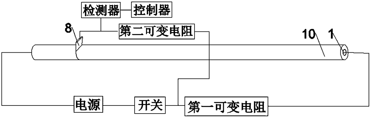
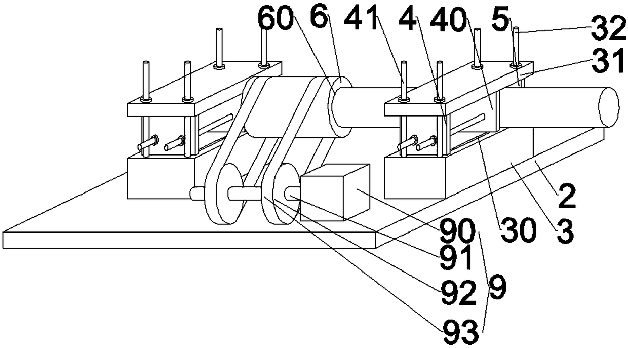
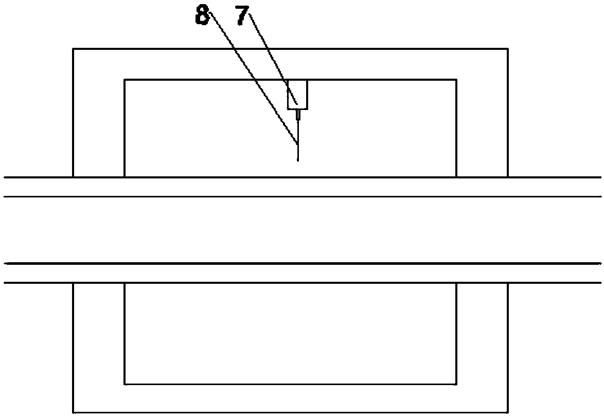
[0032] Such as Figure 1-4 As shown, the present invention provides a rotary intelligent end stripper. The wire to be stripped includes a wire body 1 and an insulating sheath 10 coated outside the wire body 1, including:

[0033] Base 2;

[0034]A pair of fixing mechanisms, each fixing mechanism includes a cuboid horizontal seat 3 fixed on the base 2, and the top of the horizontal seat 3 is vertically fixed respectively near its opposite two edges (the opposite two edges along the length direction). The first telescopic plate 4, the top of the two first telescopic plates 4 is f...


PUM


Abstract

The invention discloses a rotary intelligent end stripper, which comprises a base, a pair of fixing mechanisms, a cutting mechanism, a rotating mechanism and a supporting mechanism, wherein the cutting mechanism comprises a hollow roller; a telescopic motor is arranged on the inner side wall of the roller; a free end of an output shaft of the telescopic motor is fixedly connected to a double-cutting knife with a bottom blade and a side blade; the double-cutting knife is arranged above a to-be-stripped part; the telescopic motor stretches to drive the bottom blade of the double-cutting knife tocut the to-be-stripped part along the radial direction; a rotating motor rotates to drive the side blade of the double-cutting knife to cut the to-be-stripped part along the circumferential direction; the supporting mechanism comprises a supporting seat arranged below the roller, a roller which can be fixed above the roller along the circumferential direction in a rotary sheathed manner; and theouter side wall of the roller is detachably arranged above the supporting seat. The rotary intelligent end stripper has the following beneficial effects that the deformation degree of an insulating cover caused by clamping is relieved through four-point symmetric clamping, and meanwhile, the to-be-stripped part is cut in a synchronous rotary propulsion manner, so that the cutting error caused by wire deformation due to the traditional press-in operation is avoided.

Description

technical field [0001] The invention relates to the technical field of printing equipment. More specifically, the present invention relates to a rotary smart end stripper. Background technique [0002] Wires are widely used in life, industry, military and other fields. Generally, the conductive core of the wire is wrapped by an insulating sheath. The insulating sheath is usually made of polyvinyl chloride. When wiring, it is usually necessary to peel off the sheath at the end of the wire to make it conductive. The core is exposed, so that the conductive core is connected to other conductors for energization. In order to peel off the outer skin of the wire end smoothly, there are two conventional peeling methods: incineration and mechanical peeling. Softened and not connected to the conductive core wrap, quickly tear it off with your hands or other tools before it cools down, but the stripped skin is easy to stick to your hands or tools, which will affect the use of tools or...

Claims


Application Information

Patent Timeline
Patent Type & Authority Applications(China)
IPC IPC(8): H01R43/28G01R31/02
CPCG01R31/50H01R43/28
Inventor 王和平
Owner 北海市天硌打印耗材有限公司
Why Eureka
Try Eureka