Workpiece machining method and workpiece machining device

A processing method and workpiece technology, applied in metal processing machinery parts, feeding devices, metal processing, etc., can solve problems such as cutting surface errors, and achieve the effect of reducing cutting errors

Pending Publication Date: 2021-11-26
SHIBAURA MASCH CO LTD
View PDF8 Cites 2 Cited by
  • Summary
  • Abstract
  • Description
  • Claims
  • Application Information

AI Technical Summary

Problems solved by technology

[0009] As described above, in the conventional example disclosed in Patent Document 1, there is a problem that when the arc center of the arc-shaped corner portion of the round nose milling cutter deviates, it cannot be corrected, and the surface error

Method used


Image

  • Workpiece machining method and workpiece machining device
  • Workpiece machining method and workpiece machining device
  • Workpiece machining method and workpiece machining device

Examples


Embodiment Construction

[0023] [Description of configuration of this embodiment]

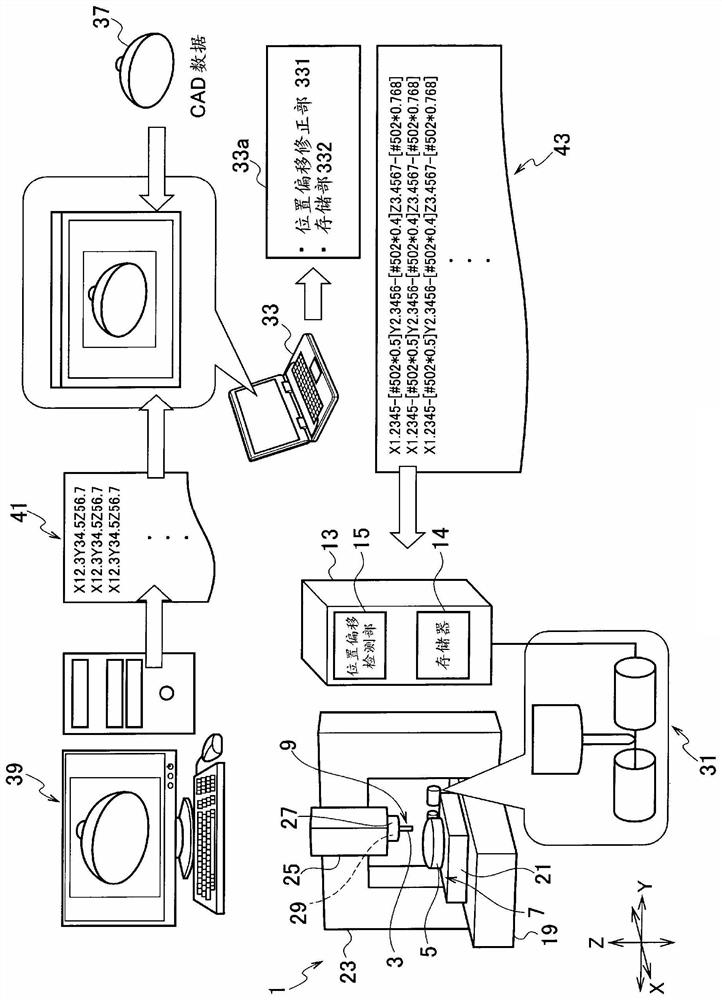
[0024] Hereinafter, a workpiece processing device according to an embodiment will be described with reference to the drawings. figure 1 It is an explanatory diagram showing the configuration of a workpiece processing device 1 (hereinafter simply referred to as "processing device 1") according to the present embodiment. Such as figure 1 As shown, the processing device 1 is provided with: a bed 19 serving as a base; a workbench 21 provided on the upper surface of the bed 19; The pillar 23 that presents an inverted U-shape;

[0025] In addition, hereinafter, one direction set on the upper surface of the bed 19 is defined as the X-axis direction (front-rear direction), and the direction perpendicular to the X-axis direction on the upper surface of the bed 19 is defined as the Y-axis direction (left-right direction). direction), the direction perpendicular to the upper surface of the bed 19 (that is, the normal direction...


PUM


Abstract

A workpiece machining device (1) is provided with a positional displacement correction unit (331) that detects the positional displacement between a real contour line (P2) of a radius end mill (3) and an ideal contour line (P1) and corrects the positional displacement of the radius end mill (3). The positional displacement correction unit (331) calculates a first correction value for aligning the center of a first circular-arc portion forming a circular-arc shape in a corner portion of the ideal contour line (P1) with the center of a second circular-arc portion forming a circular-arc shape in a corner portion of the real contour line (P2) in a plane orthogonal to the rotation axis, and corrects a machining point of the radius end mill (3) using the first correction value.

Description

technical field [0001] The invention relates to a workpiece processing method and a workpiece processing device. Background technique [0002] Conventionally, a workpiece processing apparatus has been used that uses an NC program to relatively move an end mill to a workpiece (material to be processed), and to rotate the end mill to perform cutting processing on the workpiece. [0003] In such a machining device, the end mill is clamped and fixed to a tool holding portion such as a spindle, moved relative to a workpiece, and then cutting is performed. Therefore, a positional shift occurs when the end mill is fixed to the tool holding portion due to poor clamping or the like. In addition, initial shape errors may occur in the end mill. In such a case, there is a problem that the end mill cannot be moved to an accurate cutting position with respect to the workpiece, and high-precision cutting cannot be performed. [0004] In addition, Patent Document 1 discloses that when ma...

Claims


Application Information

Patent Timeline
Patent Type & Authority Applications(China)
IPC IPC(8): B23Q17/22G05B19/404B23Q15/00
CPCG05B19/404B23Q17/22B23C3/16G05B19/40937G05B2219/37228G05B2219/50285G05B2219/50293G05B2219/50334Y02P90/02B23C5/1009B23C9/00B23Q15/00G05B19/4093B23C5/10B23Q15/22G05B19/402G05B19/4099
Inventor 土屋康二
Owner SHIBAURA MASCH CO LTD
Why Eureka
Try Eureka