Panel display glass cutting system and method
A flat-panel display glass and cutting system technology, applied in glass cutting devices, glass production, glass manufacturing equipment, etc., can solve the problems of low production efficiency of flat-panel display glass, reduce production accidents, smooth the production process, and improve safety. Effect
- Summary
- Abstract
- Description
- Claims
- Application Information
AI Technical Summary
Problems solved by technology
Method used
Image

Examples
Embodiment 1
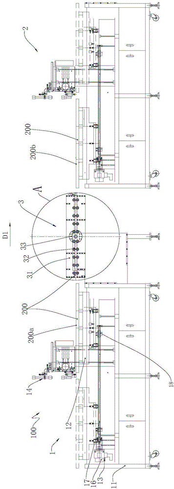
[0032] Such as Figure 1 to Figure 3 Shown is a preferred embodiment provided by the present invention.
[0033] For the convenience of description, the "left", "right", "upper" and "lower" referred to below are consistent with the left, right, up and down directions of the drawings themselves, but do not limit the structure of the present invention.
[0034] This embodiment provides a cutting system 100 for flat panel display glass, including a first glass cutting machine 1 , a second glass cutting machine 2 and a horizontal turning machine 3 arranged side by side and alternately.
[0035] The first glass cutting machine 1 is used for the feeding of the feeder (not shown in the figure), and the A side (i.e. the first surface 200a) of the glass to be processed 200 after the feeding is collectively referred to as the first surface hereinafter for the purpose of unifying technical terms. 200a) for cutting, see Figure 1 to Figure 3 , the first glass cutting machine 1 includes ...
Embodiment 2
[0044] Only the differences from Embodiment 1 are described in detail below:
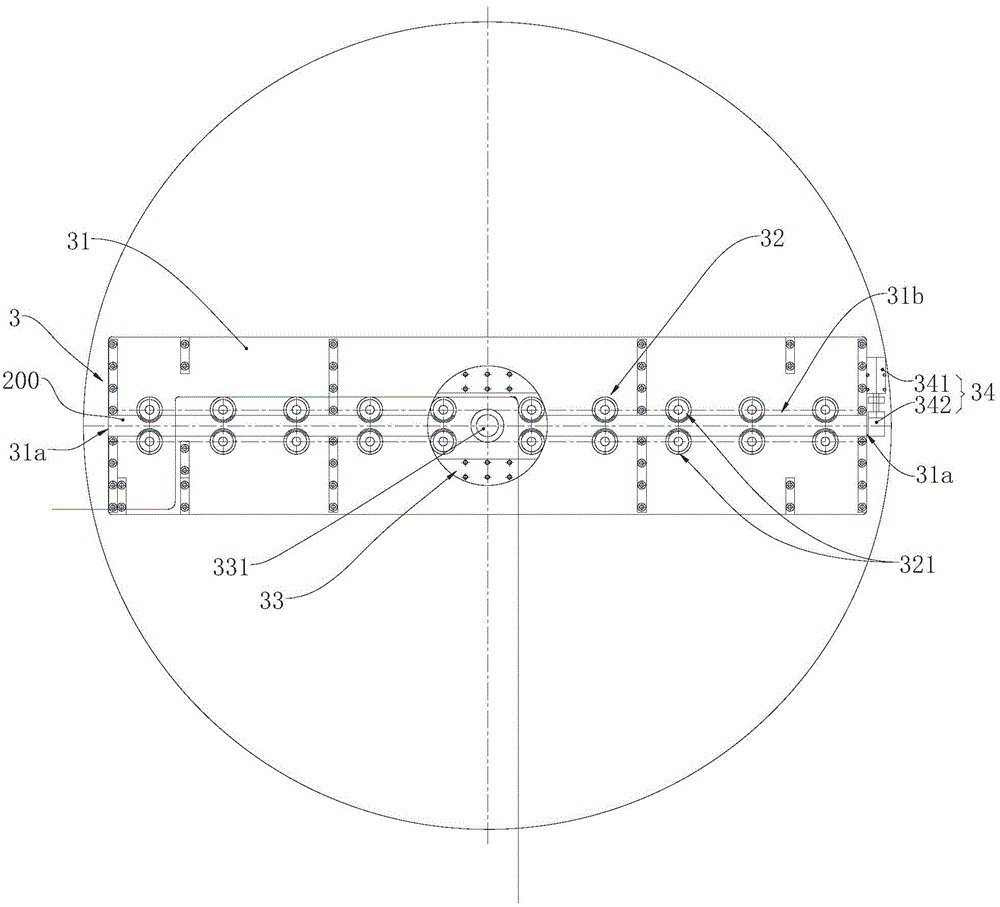
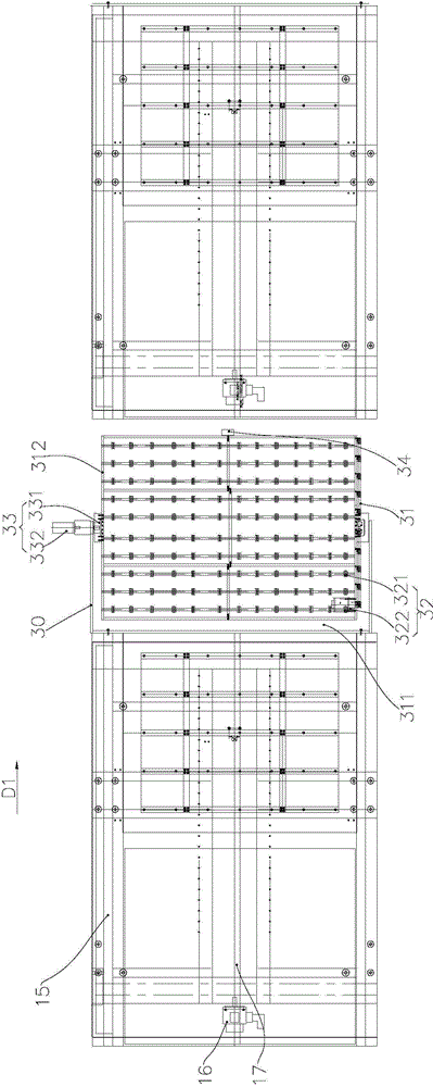
[0045] In this embodiment, the width of the reversing frame 31 is slightly longer than that of the glass 200 to be processed, and its length is two parts of the length of the glass 200 to be processed. The space 31b is provided with a position locking assembly 34, which is roughly located in the middle of the length of the reversing frame 31, and the two ports 31a of the reversing frame 31 can allow the glass 200 to be processed to enter and send out. The glass 200 to be processed enters the inner space 31 b of the turning frame 31 through one of the ports 31 a and stops when it moves to the position locking assembly 34 . When the overturning frame 31 rotates, the end close to the first glass cutting machine 1 rotates upwards around the overturning shaft 331. In this way, after the overturning frame 31 is overturned once, it is not necessary to turn 180 degrees to allow the next glass to be processe...
Embodiment 3
[0047] Only the differences from the previous two embodiments are described in detail below:
[0048] In this embodiment, the length and width of the turning frame 31 are slightly longer than the glass 200 to be processed, and the turning shaft 331 is installed on the second side 312 of the turning frame 31 away from the end of the first glass cutting machine 1. The port 31 a of the first glass cutting machine 1 is provided with a position locking assembly 34 , and when the turning frame 31 rotates, the end close to the first glass cutting machine 1 rotates upward around the turning shaft 331 .
[0049] Of course, the position locking assembly 34 can also be installed on the reversing frame 31 near the port 31a of the first glass cutter 1, so that when the reversing frame 31 rotates, the end near the first glass cutter 1 turns downwards around the reversing shaft 331 turns. Or position locking assemblies 34 are installed at both ends of the overturning frame 31, so that the o...
PUM
 Abstract
Description
Claims
Application Information
 - R&D
- Intellectual Property
- Life Sciences
- Materials
- Tech Scout
- Unparalleled Data Quality
- Higher Quality Content
- 60% Fewer Hallucinations
Browse by: Latest US Patents, China's latest patents, Technical Efficacy Thesaurus, Application Domain, Technology Topic, Popular Technical Reports.
© 2025 PatSnap. All rights reserved.Legal|Privacy policy|Modern Slavery Act Transparency Statement|Sitemap|About US| Contact US: help@patsnap.com