Internal combustion engine valve transmission lubricating device

A transmission device and lubrication device technology, which is applied in the direction of engine lubrication, valve accessories lubrication, valve device, etc., can solve the problems of increased rotation resistance of the camshaft, deterioration of the installation of the camshaft, etc., and achieve the effect of suppressing the sound

Active Publication Date: 2016-11-23
SUZUKI MOTOR CORP
View PDF4 Cites 4 Cited by
  • Summary
  • Abstract
  • Description
  • Claims
  • Application Information

AI Technical Summary

Problems solved by technology

However, if this fitting is tightened, other problems arise in that the mountability of the camshaft (or bearing) to the bearing hole deteriorates and the rotation resistance of the camshaft increases.

Method used


Image

  • Internal combustion engine valve transmission lubricating device
  • Internal combustion engine valve transmission lubricating device
  • Internal combustion engine valve transmission lubricating device

Examples


Embodiment Construction

[0073] Hereinafter, preferred embodiments of the present invention will be described with reference to the drawings.

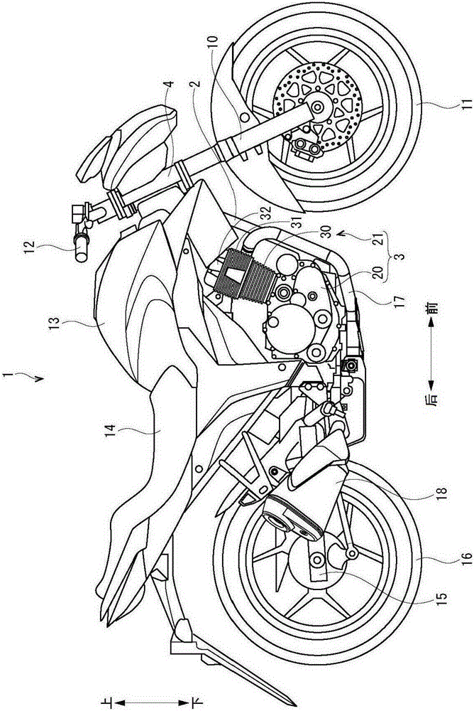
[0074] refer to figure 1 The overall structure of the motorcycle 1 will be described. figure 1 A side view of the motorcycle 1 is shown. In addition, below, each direction is set based on the occupant who rides on the motorcycle 1, and it demonstrates based on the direction shown in each figure.

[0075] The motorcycle 1 is roughly configured to include a body frame 2 and an engine 3 .

[0076] The vehicle body frame 2 is formed by welding pipes made of steel or aluminum alloy. A head pipe 4 is fixed to a front portion of the vehicle body frame 2 , and the head pipe 4 rotatably supports a pair of left and right front forks 10 . The front wheel 11 is rotatably supported on the lower portion of the front fork 10 . A handle 12 is provided on an upper portion of the front fork 10 .

[0077] A fuel tank 13 for storing fuel (such as gasoline) is provided on th...


PUM


Abstract

The present invention provides an internal combustion engine valve transmission lubricating device which inhibits the sound in the bearing portion separated from a transmission device. The device comprises: a cylinder stator vertically stand at a crankcase in an inclined posture; a valve transmission device driving a drain tap through a cam shaft extending along the width direction; a transmission device configured in a transmission chamber at one side of the width direction and connected with the and the cam shaft; and a lubrication mechanism jetting lubricating oil to lubricate the valve transmission device. The valve transmission device includes a pair of rolling bead bearing arranged at the other side of the width direction, supported at two sides of the width direction of the cam shaft and embedded at the cylinder cover for fixture. The lubrication mechanism has a guidance passage formed at the cylinder cover which is used for guide the lubricating oil of the lubricating valve transmission device to the rolling bead bearing.

Description

technical field [0001] The invention relates to a valve drive lubricating device for an internal combustion engine. Background technique [0002] An internal combustion engine is equipped with a valve train that drives intake and exhaust valves via a camshaft that rotates around an axis. [0003] For example, the engine described in Patent Document 1 includes: an engine main body consisting of a crankcase, a cylinder block, and a cylinder head; and a timing belt (cam chain) that connects a crankshaft supported by a crankcase and a camshaft in a synchronous transmission chamber formed on one side of the engine main body. Both ends of the camshaft are pivotally supported by pocket-shaped bearing holes formed in the other wall of the cylinder head and ball bearings fitted in a partition wall adjacent to the synchronous transmission chamber. [0004] The valve transmission lubricating device for an engine described in Patent Document 1 is configured to include an oil slinger p...

Claims


Application Information

Patent Timeline
Patent Type & Authority Applications(China)
IPC IPC(8): F01L1/46F01M9/10F02F1/40
CPCF01L1/46F01M9/102F02F1/40
Inventor 梶野雄稔
Owner SUZUKI MOTOR CORP
Why Eureka
Try Eureka