Urea injection components

A technology of urea injection and components, which is applied in the direction of pump components, engine components, variable capacity pump components, etc., can solve problems such as installation and positioning, and achieve the effect of solving installation and positioning

Active Publication Date: 2019-07-09
TENNECO SUZHOU EMISSION SYST
View PDF7 Cites 0 Cited by
  • Summary
  • Abstract
  • Description
  • Claims
  • Application Information

AI Technical Summary

Problems solved by technology

[0004] However, due to the large number of sensors, how to install and position them is also a technical problem in the industry

Method used


Image

  • Urea injection components
  • Urea injection components
  • Urea injection components

Examples


Embodiment Construction

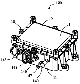
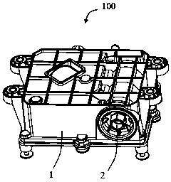
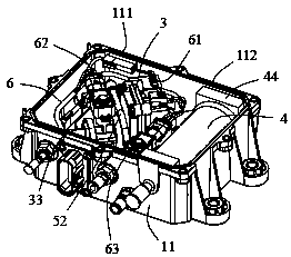
[0044] Please refer to Figure 1 to Figure 9 As shown, the present invention discloses a urea injection assembly 100, which includes a housing 1, a filter assembly 2 located in the housing 1, a pump assembly 3 for pumping urea solution, and a heating device with a heating and defrosting function. Component 4, and wire harness component 6, etc. In the illustrated embodiment of the present invention, the urea injection assembly 100 is applied in an air-assisted urea injection assembly, which includes a liquid circuit 101 (refer to Figure 4 shown by the solid arrow in ) and air path 102 (refer to Figure 4 indicated by the hollow arrow in ). It can be understood that the liquid path 101 and the gas path 102 finally converge to a nozzle (not shown) to spray atomized urea solution into the exhaust pipe to purify the exhaust gas. As for the way of converging the liquid path 101 and the gas path 102, there are generally two ways of internal mixing and external mixing, which are w...


PUM


Abstract

A urea jetting assembly comprises a shell body, a harness assembly and a pump assembly. The pump assembly comprises a pump shell and a pump in the pump shell; the pump shell comprises a protruding portion extending upwards, and the protruding portion comprises a groove penetrating up and down, a stopping portion on one side of the groove and a second insert hole penetrating upwards; the shell body is provided with an installing boss, and the installing boss comprises a notch, a stopping wall located on the notch and a first insert hole located under the concaving opening; the harness assembly comprises a first pressure sensor installed on the protruding portion and a second pressure sensor installed on the installing boss; the first pressure sensor is clamped in the groove after rotation; and the second pressure sensor is clamped in the notch after rotation, installing and positioning of the sensors are achieved.

Description

technical field [0001] The invention relates to a urea injection assembly, which belongs to the technical field of aftertreatment of engine exhaust gas. Background technique [0002] Existing urea injection systems include air-assisted and non-air-assisted. Among them, the non-air-assisted urea injection system usually includes a pump, a filter, a metering nozzle connected to the pump, and several sensors. This kind of urea injection system often has very high requirements on the metering nozzle. Since the metering nozzle is installed on the exhaust pipe, it is easy to affect the metering accuracy due to the high temperature of the exhaust gas, and even be burned out by high temperature. In addition, the urea solution will freeze and expand in volume under cold conditions. Therefore, how to empty the residual urea solution in the system and reduce the risk of the system being damaged by freezing is also a problem that needs to be solved for this system. [0003] The air-as...

Claims


Application Information

Patent Timeline
Patent Type & Authority Patents(China)
IPC IPC(8): F01N3/28F01N13/18F04B53/16F04B53/08
Inventor 樊坚强童毅周林
Owner TENNECO SUZHOU EMISSION SYST
Why Eureka
Try Eureka