A gearbox overdrive shifting power-assisted shifting mechanism and its use method

A shifting mechanism and overdrive technology, applied to controlled components, mechanical equipment, mechanical control devices, etc., to achieve the effects of reduced design costs, simple structure, and smooth shifting operations

Active Publication Date: 2018-07-10
DONGFENG COMML VEHICLE CO LTD
View PDF8 Cites 0 Cited by
  • Summary
  • Abstract
  • Description
  • Claims
  • Application Information

AI Technical Summary

Problems solved by technology

[0005] The purpose of the present invention is to overcome the problem in the prior art that an additional reversing device needs to be added inside the gearbox, and provides a gearbox overdrive gear conversion power-assisted shifting mechanism without adding a reversing device inside the gearbox and its Instructions

Method used


Image

  • A gearbox overdrive shifting power-assisted shifting mechanism and its use method
  • A gearbox overdrive shifting power-assisted shifting mechanism and its use method
  • A gearbox overdrive shifting power-assisted shifting mechanism and its use method

Examples


Embodiment 1

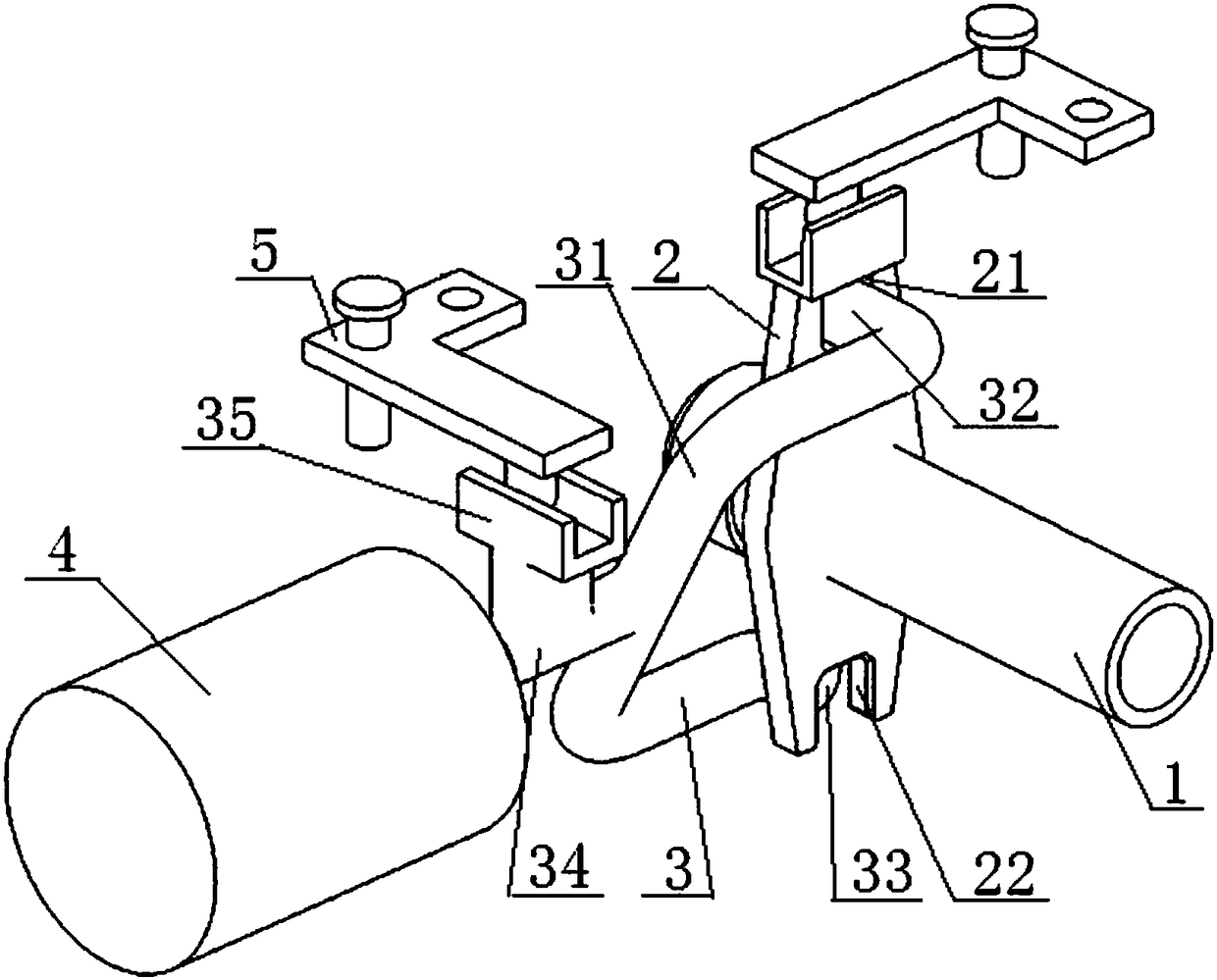
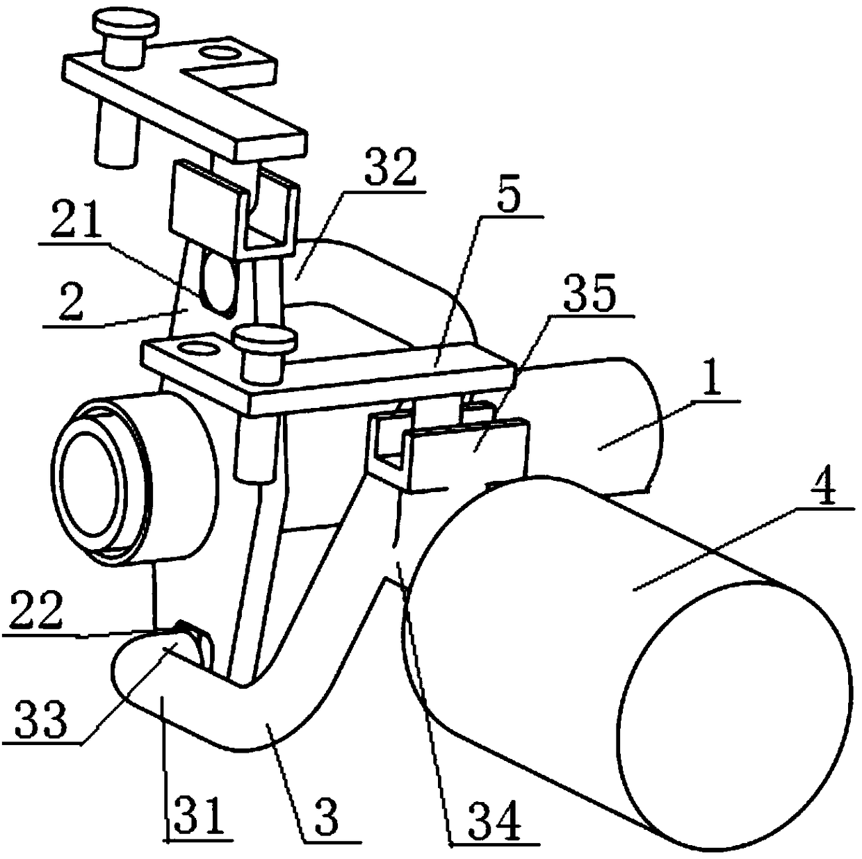
[0072] see Figure 1 to Figure 3, a gearbox overdrive shifting power-assisted shifting mechanism, comprising a gearbox selector shift shaft 1 and a selector shift rocker 2 fixedly connected thereto, one end of the gearbox selector shift shaft 1 passes through the selector shift rocker The arm 2 is in transmission with the shift flexible shaft, and the other end of the transmission selector shaft 1 is in transmission cooperation with the shift fork shaft; the middle part of the selector shift rocker arm 2 is fixedly connected with the transmission selector shift shaft 1, The upper and lower ends of the selector shift rocker arm 2 are in transmission cooperation with the shift fork 3, and the shift fork 3 includes a U-shaped fork lever 31, a general gear selector lever 32 and a direct gear overdrive selector lever 33. Both the general gear selector lever 32 and the direct gear overdrive selector lever 33 are arranged parallel to the gearbox selector shift shaft 1, and one end of...

Embodiment 2

[0086] Embodiment 2 is basically the same as Embodiment 1, and its difference is:

[0087] The end faces of the general gear selector lever 32 and the direct gear overdrive selector lever 33 are both arc-shaped structures.

Embodiment 3

[0089] Embodiment 3 is basically the same as Embodiment 1, and its difference is:

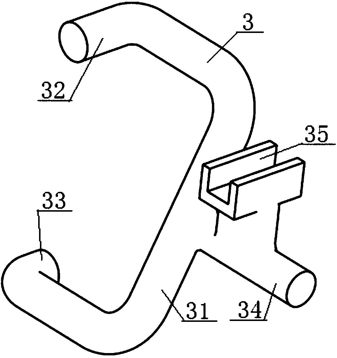
[0090] The shift fork 3 also includes a U-shaped transmission slot 35, the bottom of the U-shaped transmission slot 35 is fixedly connected with the middle part of the transmission push rod 34, and the U-shaped transmission slot 35 is parallel to the gear selection of the gearbox. Shaft 1 is set, and the shift flexible shaft passes through the L-shaped transmission plate 5, the U-shaped transmission groove 35, the transmission push rod 34 and the U-shaped fork rod 31 in sequence; the L-shaped transmission plate 5 includes a vertically connected second A transmission plate 51 and a second transmission plate 52, the end of the first transmission plate 51 is provided with a gear selection flexible shaft installation position 53, and the end of the second transmission plate 52 is provided with a dial block 54, the dial The block 54 is arranged inside the U-shaped transmission groove part 35, and th...


PUM


Abstract

The invention discloses a transmission overgear boost shifting mechanism which comprises a transmission gear selection and shifting shaft and a gear selection and shifting rocker arm. One end of the transmission gear selection and shifting shaft is in transmission fit with a gear shifting flexible shaft through the gear selection and shifting rocker arm. The middle of the gear selection and shifting rocker arm is fixedly connected with the transmission gear selection and shifting shaft. The upper end and the lower end of the gear selection and shifting rocker arm are both in transmission fit with a gear shifting fork. The upper end and the lower end of a U-shaped rod jaw of the gear shifting fork are connected with one end of a common gear selection lever and one end of a direct gear and overgear selection lever correspondingly, and the common gear selection lever and the direct gear and overgear selection lever are parallel to each other. The other end of the common gear selection lever is in insertion fit with a first gear shifting hole in the upper end of the gear selection and shifting rocker arm. The other end of the direct gear and overgear selection lever is in insertion fit with a second gear shifting hole in the lower end of the gear selection and shifting rocker arm. The middle of the U-shaped rod jaw is in transmission fit with the gear shifting flexible shaft. By the adoption of the design, the transmission overgear boost shifting mechanism is simple in structure and low in manufacturing cost, and transmission gear sequence reversion can be realized without changing the internal structure of a transmission.

Description

technical field [0001] The invention relates to a gear selection and shifting structure of a gearbox, in particular to a gear shifting mechanism for over-speed shifting of a gearbox and a use method thereof, and is particularly suitable for simplifying the gear-shifting structure of an over-speed gear of a gearbox. Background technique [0002] With the vigorous development of the automobile market, a basic gearbox needs to be equipped with two or more speed ratios of direct gear and overdrive gear to meet the needs of market segments. Moreover, as the market's requirements for the comfort of automobile shifting increase, the shift assist system is also more and more widely used in the transmission shifting system, especially in the commercial vehicle market. Since the gear arrangement of the overdrive gearbox is different from that of the direct transmission, the control mechanism used in the original direct transmission gearbox cannot be directly adapted to the overdrive g...

Claims


Application Information

Patent Timeline
Patent Type & Authority Patents(China)
IPC IPC(8): F16H59/04F16H63/32
CPCF16H59/04F16H63/32
Inventor 占伟李杰李瑾宁杜春鹏邱华王树彬
Owner DONGFENG COMML VEHICLE CO LTD
Why Eureka
Try Eureka