
Camera holder with lifting function

A technology of camera and pan/tilt, which is applied in the field of camera pan/tilt, which can solve the problems of affecting the function of the encoder, the large size of the camera pan/tilt, and the inability to accurately control the lifting height, etc., and achieve the effect of low cost, small size and beautiful appearance

Active Publication Date: 2016-11-23
江苏哈工智新科技股份有限公司
View PDF5 Cites 2 Cited by
  • Summary
  • Abstract
  • Description
  • Claims
  • Application Information

AI Technical Summary

Problems solved by technology

[0002] In order to precisely control the lifting height of the camera pan / tilt, most of the existing camera pan / tilts use servo motors, but the servo motors are expensive, which greatly increases the cost of the camera pan / tilt
In addition, in order to hide the wiring of the upper pan / tilt camera, most of them use spring wires to expand and contract. This setting makes the camera pan / tilt too bulky, which will affect the function of the encoder, and cannot accurately control the height of the lift

Method used

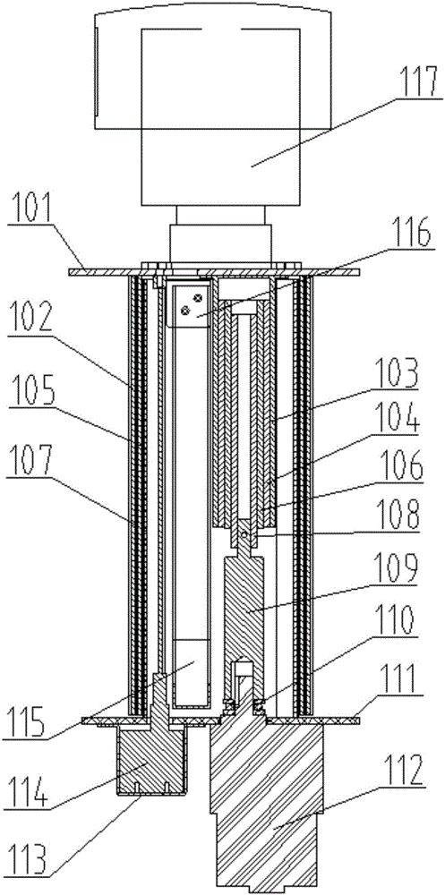

Image

  • Camera holder with lifting function
  • Camera holder with lifting function
  • Camera holder with lifting function

Examples


Embodiment Construction

[0014] Such as Figure 1-2 As shown, the camera head with lifting function according to the present invention includes an upper base plate 101, a lower base plate 111, a circular joint column, a screw rod, an adapter sleeve 109, a motor 112, an encoder 114, and an encoder bracket 113, towline 115, towline bracket 116, pan-tilt camera 117, bearing 110; the upper surface of the upper base plate 101 is equipped with a pan-tilt camera 117, and the lower surface of the upper base plate 101 is fixedly connected with a circular joint column, a screw rod and a drag chain bracket 116. The circular section column includes an outer section column 102, a middle section column 105 and an inner section column 107. The three section columns are sleeved together and relatively slidingly connected. The upper end of the outer section column 102 is connected to the upper section through a countersunk bolt The base plate 101 is fixedly connected, the lower end of the inner section column 107 is f...


PUM


Abstract

The invention discloses a camera holder with a lifting function. A lifter is that a direct current motor drives a screw rod to rotate; the screw transmission of the screw rod is changed into linear motion of the camera holder in the vertical direction; a bracing wire encoder is additionally arranged in the lifter so as to realize position feedback; and an STM32 development plate arranged in the direct current motor is used for accurately controlling the lifting height of the camera holder.

Description

technical field [0001] The invention relates to the field of robots, in particular to a camera platform with lifting function. Background technique [0002] In order to accurately control the lifting height of the camera platform, most of the existing camera platforms use servo motors, but the servo motors are expensive, which greatly increases the cost of the camera platform. In addition, in order to hide the wiring of the upper gimbal camera, most of them use spring wires to expand and contract. Such a setting makes the camera gimbal too bulky, which will affect the function of the encoder, and cannot accurately control the height of the lift. Contents of the invention [0003] The invention provides a camera pan-tilt with a lifting function, which uses a DC motor with a lower price and is used in conjunction with a cable encoder to accurately control the height of the lifting according to requirements. At the same time, the wiring of the pan-tilt camera is hidden. The ...

Claims


Application Information

Patent Timeline
Patent Type & Authority Applications(China)
IPC IPC(8): F16M11/28
CPCF16M11/28
Inventor 乔徽张兆东陆震宇
Owner 江苏哈工智新科技股份有限公司
Learn More