
A method and equipment for making multi-scale and multi-shape rock fractures with controllable roughness
A technology of rock fissures and roughness, applied in the field of rock mechanics experiments in civil engineering, can solve problems such as uncontrollable fissure roughness, and achieve the effect of controllable roughness and improved success rate
- Summary
- Abstract
- Description
- Claims
- Application Information
AI Technical Summary
Problems solved by technology
Method used
Image

Examples
example 1
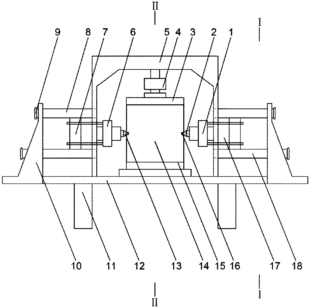
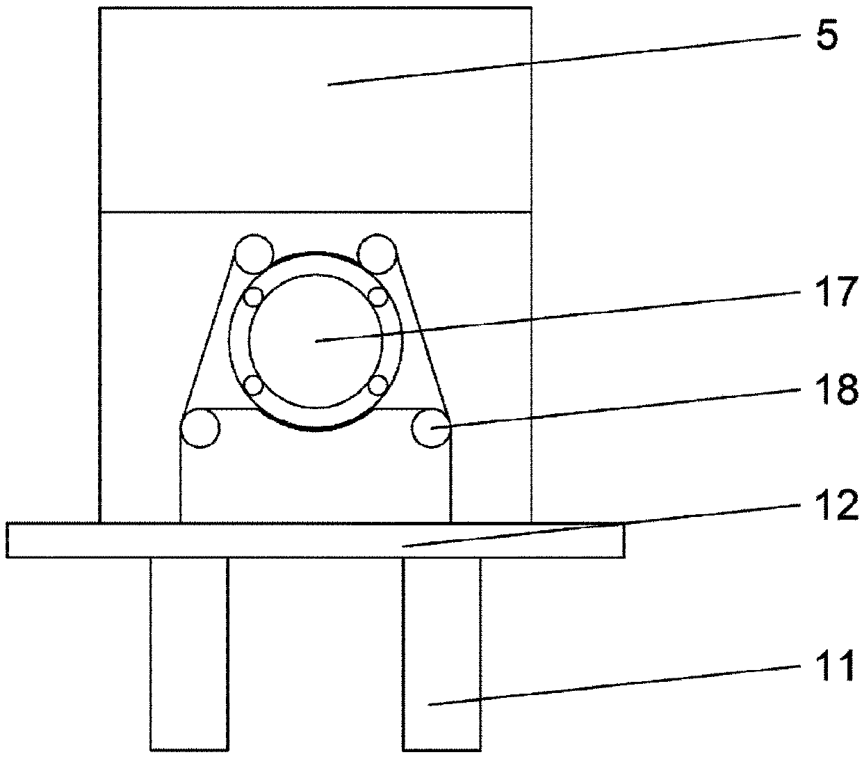
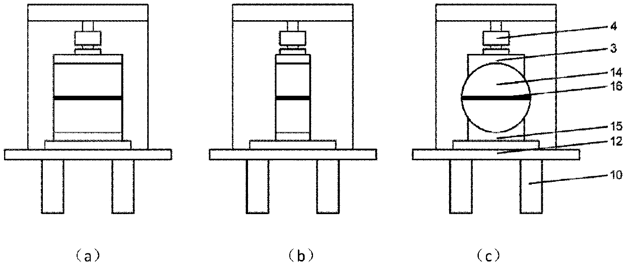
[0052] Example 1: A method for making multi-scale and multi-shaped rock fractures with controllable roughness, taking a granite cube specimen with a side length of 400mm as an example, including the following steps:
[0053] Step 101: First, select a backing plate 15 with a side length of 400 mm and a fixture 3 with a side length of 400 mm according to the size of the specimen
[0054] Step 102: Stack the backing plates to ensure that the centerline of the test piece is on the centerline of the lateral loading device.
[0055] Step 103: Make a groove of 10mm×10mm×400mm at the center line of both sides of the test piece.
[0056] Step 104: Stack and place fixture 3 on top of the test piece, start vertical loading device 4, apply pressure at a rate of 0.5 MPa / min, and apply a normal stress of 20 MPa to the test piece according to the required crack roughness.
[0057] Step 105: After the normal stress is stabilized, start the lateral pushing device, push the lateral loading dev...
example 2
[0060] Example 2: A method for making multi-scale and multi-shaped rock fractures with controllable roughness, taking the vertical placement of a cylinder with a diameter of 200mm and a height of 400mm as an example, including the following steps:
[0061] Step 201: First, select a circular backing plate 15 with a diameter of 200 mm and a circular fixture 3 with a diameter of 200 mm according to the size of the test piece
[0062] Step 202: Stack the backing plates to ensure that the centerline of the test piece is on the centerline of the lateral loading device.
[0063] Step 203: Make a groove of 10mm×10mm×125mm at the center line of both sides of the test piece.
[0064] Step 204: Stack and place the fixture 3 on the top of the specimen, start the vertical loading device 4, pressurize at a rate of 0.5 MPa / min, and apply a normal stress of 15 MPa to the specimen according to the required crack roughness.
[0065] Step 205: After the normal stress is stabilized, start the la...
example 3
[0068] Example 3: A method for making multi-scale and multi-shaped rock fractures with controllable roughness, taking the lateral placement of a cylinder with a diameter of 200mm and a height of 400mm as an example, including the following steps:
[0069] Step 301: First, according to the size of the test piece, select a backing plate 15 with a side length of 160 mm and an arc-shaped diameter of 200 mm and a fixture 3 of the same size.
[0070] Step 302: Stack the backing plates to ensure that the centerline of the test piece is on the centerline of the lateral loading device.
[0071] Step 303: Make a groove of 10mm×10mm×400mm at the center of the two sides of the test piece.
[0072] Step 304: Stack and place the fixture 3 on the top of the test piece, start the vertical loading device 4, pressurize at a rate of 0.5 MPa / min, and apply a normal stress of 15 MPa to the test piece according to the required crack roughness.
[0073] Step 305: After the normal stress is stabiliz...
PUM
 Abstract
Description
Claims
Application Information