Plasma display panel and method for making a plasma display panel

Inactive Publication Date: 2005-12-01
SAMSUNG SDI CO LTD
View PDF0 Cites 12 Cited by
  • Summary
  • Abstract
  • Description
  • Claims
  • Application Information

AI Technical Summary

Benefits of technology

[0010] The present invention is directed to a plasma display panel (“PDP”) comprising a MgO protection layer having a controlled surface roughness within a specified range. Such

Problems solved by technology

Sputtering provides a denser protection layer with improved

Method used


Image

  • Plasma display panel and method for making a plasma display panel
  • Plasma display panel and method for making a plasma display panel
  • Plasma display panel and method for making a plasma display panel

Examples


example 1

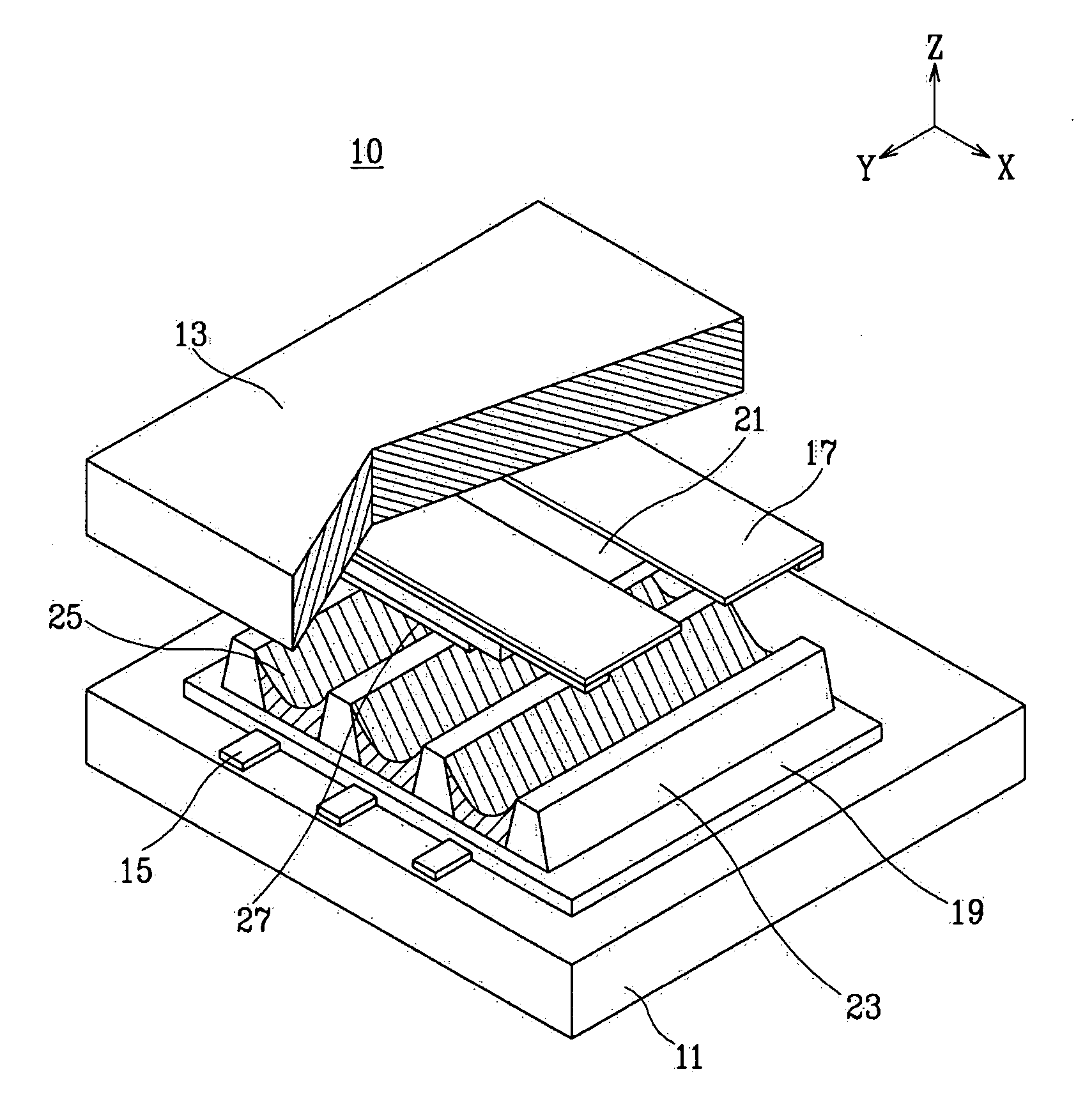
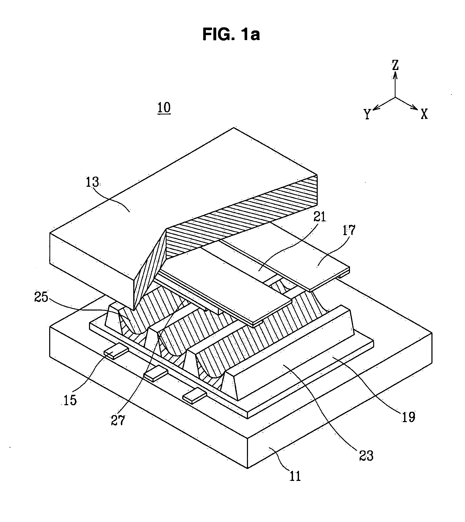
[0052] Discharge sustain electrodes comprising indium tin oxide conductive materials were positioned on a second substrate in a striped pattern. The second substrate comprised soda lime glass.

[0053] Then, a lead-based glass paste was coated on the second substrate over the discharge sustain electrodes and sintered to form a second dielectric layer.

[0054] A MgO protection layer having a surface roughness (Rms) of 60 {acute over (Å)} was ion plated to the second dielectric layer, thereby forming a second substrate. The surface roughness was controlled by varying the temperature, reaction rate, and gas partial pressure, and was analyzed by atomic force microscopy (AFM).

example 2

[0055] A second substrate was fabricated as in Example 1, except that the surface roughness (Rms) of the MgO protection layer was 88 {acute over (Å)}.

example 3

[0056] A second substrate was fabricated as in Example 1, except that the surface roughness (Rms) of the MgO protection layer was 150 {acute over (Å)}.


PUM


Abstract

A plasma display panel comprising first and second substrates positioned substantially parallel to each other, facing each other and separated from each other by a predetermined distance is disclosed. A plurality of address electrodes are formed on the first substrate. A first dielectric layer covers the address electrodes on the first substrate. A plurality of barrier ribs having predetermined heights are mounted on the first dielectric layer, creating discharge spaces between the first and second substrates. Phosphor layers are formed within the discharge spaces. A plurality of discharge sustain electrodes are formed on the second substrate and are positioned perpendicular to the address electrodes on the first substrate. A second dielectric layer is formed on the second substrate covering the discharge sustain electrodes. A MgO protection layer having a surface roughness (Rms) ranging from about 60 to about 250 {acute over (Å)} covers the second dielectric layer.

Description

CROSS-REFERENCE TO RELATED APPLICATION [0001] This application claims priority to and the benefit of Korean Patent Application No. 10-2004-0037269 filed on May 25, 2004 in the Korean Intellectual Property Office, the entire content of which is incorporated herein by reference. FIELD OF THE INVENTION [0002] The present invention relates to a plasma display panel, and more particularly, to a plasma display panel comprising a MgO protection layer capable of improving electron emission by controlling surface roughness and increasing surface area. BACKGROUND OF THE INVENTION [0003] Generally, plasma display panels (“PDP”s) are display devices in which ultraviolet rays excite phosphors in vacuum, thereby creating gas discharge in discharge cells. PDPs are the next-generation thin-film display devices and can be manufactured with large high-resolution screens. [0004] PDPs display letters or graphics using the light emitted from the plasma generated upon discharging the gas. That is, plasma...

Claims


Application Information

Patent Timeline
IPC IPC(8): H01J11/12H01J11/22H01J11/24H01J11/26H01J11/34H01J11/36H01J11/38H01J11/40H01J11/42
CPCH01J11/40H01J11/12B26F1/32G03G21/10
Inventor KIM, KI-DONG
Owner SAMSUNG SDI CO LTD
Why Eureka
Try Eureka