Laser-cleaving of an optical fiber array with controlled cleaving angle

Active Publication Date: 2021-12-02
CORNING RES & DEV CORP
View PDF0 Cites 0 Cited by
  • Summary
  • Abstract
  • Description
  • Claims
  • Application Information

AI Technical Summary

Benefits of technology

The patent describes a way to break optical fibers in an array using a laser. The process involves removing the outer coating from a section of the fiber and securing it in a holder. The holder is then aligned in the laser-cleaving apparatus. The laser cuts the fiber ends and the free ends are then mechanically separated, resulting in a cleaned and organized array of optical fibers. The process allows for flexible and precise cleaving along the fiber ribbon or cable, with minimal damage to the fiber ends and high yield.

Problems solved by technology

However, large glass roll-off variations in the flatness of the core region of the optical fiber and variations in cleave length and angles are challenges for this method.
However, polishing is time consuming and generally increases the cost of the final product.
Also, while multiple fibers can be secured in a holder to increase the efficiency of the polishing step, it can be difficult to consistently achieve the same polishing angle on the end-faces of all the fibers.
However, due to the large beam size (i.e., longer wavelength) and thermal effects that melt rather than cleave the optical fiber, there are difficulties to reduce the heat affected zone and to minimize swelling of the optical fiber during cleaving.

Method used


Image

  • Laser-cleaving of an optical fiber array with controlled cleaving angle
  • Laser-cleaving of an optical fiber array with controlled cleaving angle
  • Laser-cleaving of an optical fiber array with controlled cleaving angle

Examples


example 1

Relating to Optical Fiber Array 124 Having a 0° Cleave Angle (Flat Optical Fiber End-Face 127

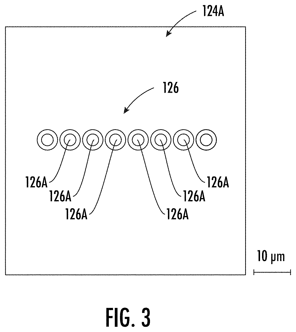
[0064]FIGS. 3 and 6A-9B illustrate representative simulations and images for optical fiber arrays comprising single mode optical fibers that have been cleaved with a flat optical fiber end-face (i.e., 0° cleave angle). In particular, the optical fiber array underwent laser-cleaving with mechanical separation by a pressurized air jet as disclosed herein. While this Example relates to an optical fiber array containing single mode optical fibers, it is within the scope of the present disclosure that alternate types of optical fiber arrays may be used (e.g., optical fiber arrays containing multimode optical fibers) to yield the properties discussed herein.

[0065]Referring now to FIGS. 7A-7C, results of a plane-wave decomposition model simulation of Bessel beams entering an optical fiber of an optical fiber array at a perpendicular angle relative to a longitudinal axis of the optical fiber with a ...

example 2

Relating to Optical Fiber Array 124 Having a 8° Cleave Angle (Angled Optical Fiber End-Face 127)

[0070]FIGS. 10A-12 illustrate microscopic images for optical fiber arrays comprising single mode optical fibers that have been cleaved at an angle of about 8° by tilting the upper stage of the stage of the laser apparatus as discussed above. In particular, the optical fiber array underwent laser-cleaving with mechanical separation by a pressurized air jet as disclosed herein. While this Example relates to an optical fiber array containing single mode optical fibers, it is within the scope of the present disclosure that alternate types of optical fiber arrays may be used (e.g., optical fiber arrays containing multimode optical fibers) to yield the properties discussed herein.

[0071]Referring first to FIGS. 10A and 10B, a sample optical fiber array (from a ribbon cable containing 12 optical fibers) was examined under a microscope after laser-cleaving as described above and prior to mechanica...

example 3

Relating to Water Assisted Laser Angle Cleaving of Optical Fiber Array

[0074]Water assisted laser-cleaving is also suitable for making an angled cleave of an optical fiber array. Without wishing to be held to any particular theory, it is believed that by immersing the optical fiber array in liquid during laser perforation processing both sources of aberration due to index matching between the fiber and water are reduced. FIG. 13A shows a simulation of the intensity profile (seen in XZ plane) of a Bessel beam directed to the center of a tilted optical fiber end-face when assuming the optical fiber is placed in air. FIG. 13C shows the intensity profile (seen in XZ plane) of a Bessel beam launched to the center of the tilted optical fiber end-face while the optical fiber is immersed in water. When comparing FIGS. 13A and 13C, there are reduced aberrations / distortions of the laser path / direction as the laser beam passes through the optical fiber in water as compared to air.

[0075]Addition...


PUM


Abstract

The present disclosure relates to a process by which an optical fiber array is cleaved with a laser-cleaving apparatus. The coating material is stripped or removed from a section of an optical fiber array; a coated or ribbonized section of the optical fiber array is secured in a holder; the holder is aligned inside the laser-cleaving apparatus; the laser cleaves the stripped ends of the fibers in the optical fiber array; the laser-cleaved ends of the optical fibers are then mechanically separated to remove the free ends from the optical fibers in the optical fiber array, leaving a cleaved array of optical fibers. The cleaving process enables the optical fiber array to be cleaved at flexible locations along an optical fiber ribbon or optical fiber cable with no swelling, minimal cleave angle variation across the cores of the optical fibers, a controlled surface roughness of the optical fiber end-faces, and high process yield.

Description

PRIORITY APPLICATION[0001]This application claims the benefit of priority of U.S. Provisional Application No. 63 / 030,473, filed on May 27, 2020, the content of which is relied upon and incorporated herein by reference in its entirety.FIELD OF THE DISCLOSURE[0002]This disclosure relates generally to processing an optical fiber array with a laser-cleaving apparatus and more particularly, to cleaving an optical fiber array with a laser-cleaving apparatus followed by mechanical separation of the cleaved ends of the optical fibers in the optical fiber array.BACKGROUND OF THE DISCLOSURE[0003]Optical fibers are commonly used for voice, video, and data transmissions in many different settings. In these settings where optical fibers are used, there are typically many locations where fiber optic cables carrying the optical fibers connect to equipment or other fiber optic cables. For example, in Micro-Electro-Mechanical-System (MEMS) applications, optical fibers (as part of optical fiber ribbo...

Claims


Application Information

Patent Timeline
IPC IPC(8): G02B6/25G02B6/04
CPCG02B6/25G02B6/04
Inventor BICKHAM, SCOTT ROBERTSONCARBERRY, JOEL PATRICKMCCLURE, RANDY LARUEUNGARO, CRAIG JOHN MANCUSIWU, QIYUAN, LEI
Owner CORNING RES & DEV CORP
Why Eureka
Try Eureka