
Development roller of electro-photographic machine

a technology of development roller and development roller, which is applied in the field of development roller of electricphotographic machines, can solve the problems of poor adhesion between the outer layer and the inner layer, poor image grain scale, and high manufacturing cost of the development roller, so as to improve the abrasive quality, minimize migration, and improve the effect of abrasive quality

Inactive Publication Date: 2006-03-16
SAMSUNG ELECTRONICS CO LTD
View PDF5 Cites 8 Cited by
  • Summary
  • Abstract
  • Description
  • Claims
  • Application Information

AI Technical Summary

Benefits of technology

The present invention provides a development roller for an electric-photographic machine that improves abrasivity and minimizes migration of low-molecule weight materials to the surface of the roller. The development roller includes a base material made of either NBR rubber or HYDRIN rubber and an electric conductive material adjusting the electric resistivity of the roller. The roller has a smooth surface and minimal surface roughness. The development roller can be easily manufactured with a simple manufacturing process and has low electric resistivity. The invention also provides a method of manufacturing the development roller and an apparatus for irradiating ultraviolet light to adjust the friction coefficient of the roller. The electric conductive high-molecule-weight material used in the development roller has pair double bonds or a cyclic compound with electrons, and can be introduced into polyethylene oxide or polypropylene. The amount of electric conductive high-molecule-weight material used in the development roller is less than a weight percentage of the base material. The friction coefficient of the surface of the development roller is below 1.0, and the roughness of the surface is in the range from Rz 1.0 to Rz 10.

Problems solved by technology

But in this case, there is a defect that a grayscale of an image is poor because a fringing portion of the electric field of the development roller 2 is weak.
But, the conventional development rollers have the following problems.
Accordingly, a manufacturing cost of the development roller is high because of a lot of man-hours and a large defective proportion.
Particularly, when the inner layer is made of a foamed rubber, adhesion between the outer layer and the inner layer may be poor, or fine holes as a defect may be easily formed in a surface of the outer layer.
Second, in another case of adjusting the electric resistivity of the development roller by adding conductive carbon blacks to a semi-conductive rubber, there is a problem that the electric resistivity of the development roller is not uniform because the conductive carbon blacks are not dispersed uniformly in the development roller.
Accordingly, because the toner adsorbed on the surface of the development roller cannot be regulated in a predetermined amount by a regulating member, which is disposed in contact with the surface of the development roller, a thickness of a layer of the adsorbed toner is not uniform.
Thus, an image defect, such as a change of an image concentration, occurs.
Also, because the toner is received with an excessive physical stress by the development roller, the toner is degraded, and thus durability of the toner is decreased.
Because an electric charging characteristic of particles of the toner is decreased by the conductive carbon blacks added to the development roller, problems, such as a short supply of the toner or a missing image, occur.
Third, in another case of the development roller made of the semi-conductive rubber to which all antistatic agent or an electric conductive agent except the carbon blacks is added, when the development roller is not used for a long period of time, problems, such as migration, a volatilization of the low molecular electric conductive agent or a secular change of the electric resistivity of the development roller may occur.
Fourth, in another case of the development roller made of urethane rubber, since the urethane rubber is expensive, the manufacturing cost of the development roller is high.
Accordingly, when the surface of the development roller is continuously in contact with the toner for an extended period of time, there is a problem that the toner cakes thereon.

Method used


Image

  • Development roller of electro-photographic machine
  • Development roller of electro-photographic machine
  • Development roller of electro-photographic machine

Examples


Embodiment Construction

[0049] Reference will now be made in detail to the present preferred embodiments of the present invention, examples of which are illustrated in the accompanying drawings, wherein like reference numerals refer to the like elements throughout. The embodiments are described below in order to explain the present invention by referring to the figures.

[0050] From now on, an embodiment of the present invention will be described in great detail by referring to the appended drawings.

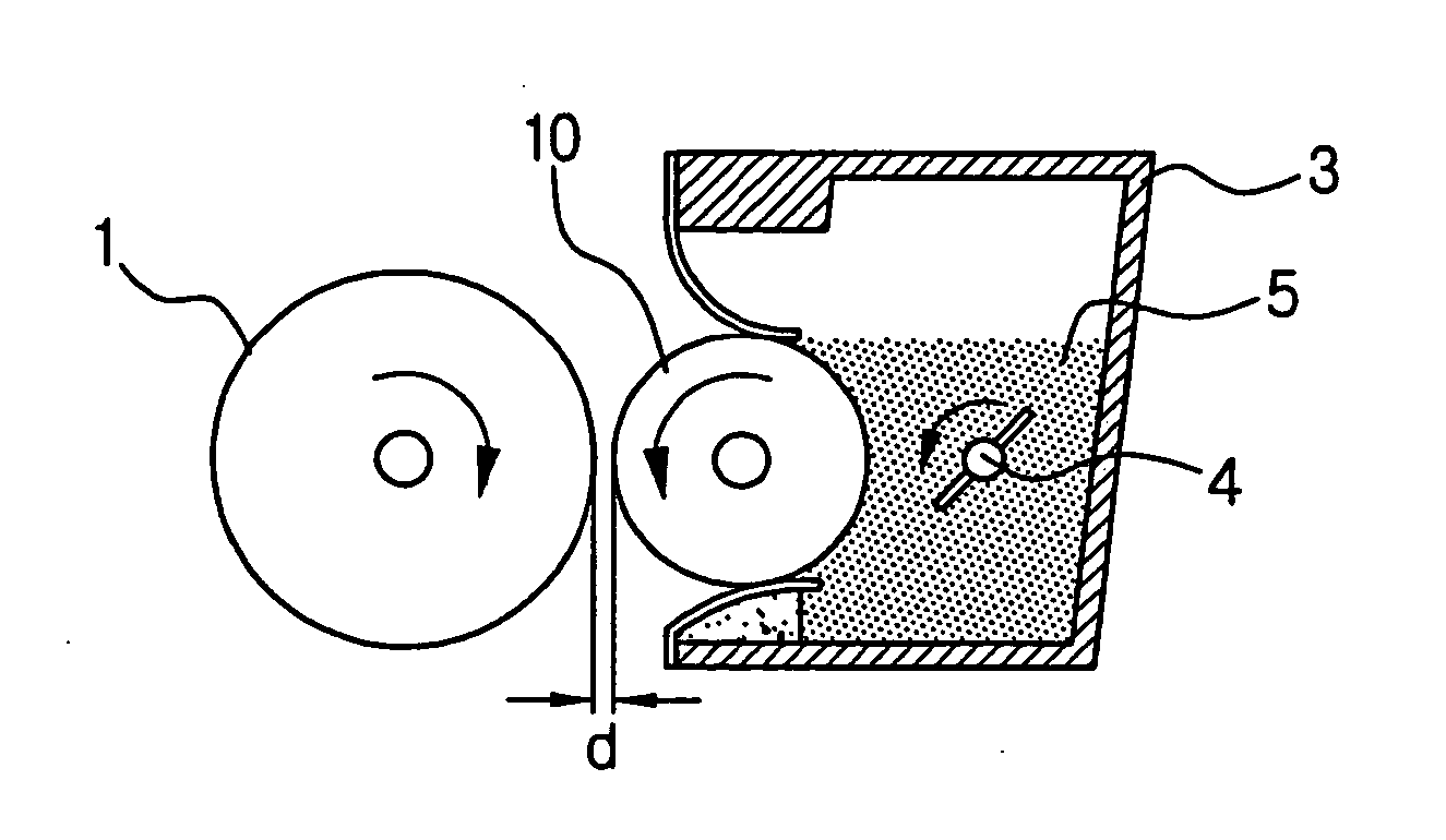
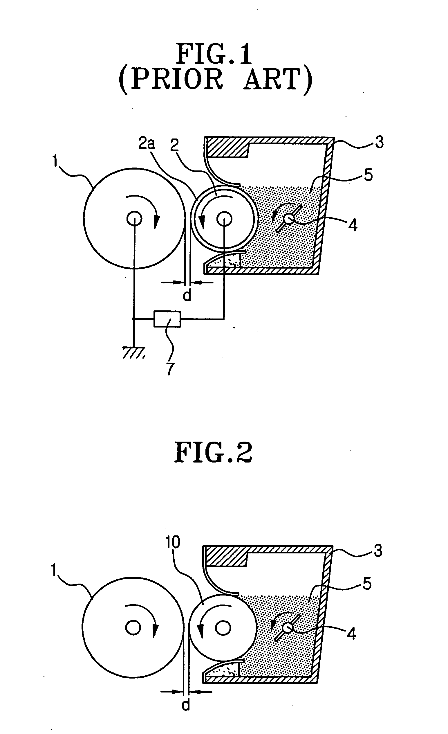
[0051] A development roller has a single layer provided coaxially on and around a shaft as illustrated FIG. 2, and includes a base material, an addition agent, and a cross-link agent. In FIG. 2, reference numerals 1, 3, 4, 5 are a photoconductive drum, a housing, an agitator, and toner, respectively.

[0052] The base material is what constitutes mainly a shape of the development roller. A rubber material that has double bonds in either a main chain or a side chain thereof and an elasticity at room temperature is...


PUM

PropertyMeasurementUnit
wavelengthaaaaaaaaaa
thicknessaaaaaaaaaa

Abstract

A development roller which supplies toner to a photoconductive drum of an electrophotographic machine includes: a base material made of at least one of an NBR rubber and an HYDRIN rubber; and a peroxide as a cross-link agent cross linking the base material in a three-dimensional reticular structure.

Description

CROSS-REFERENCE TO RELATED APPLICATIONS [0001] This application is a Divisional of application Ser. No. 10 / 277,740, filed Oct. 23, 2002, now pending.[0002] This application claims the benefit of Korean Application No. 2002-312, filed Jan. 18, 2002, in the Korean Industrial Property Office, the disclosure of which is incorporated herein by reference. BACKGROUND OF THE INVENTION [0003] 1. Field of the Invention [0004] The present invention relates to an electric-photographic machine, such as a laser printer, a photocopier or a facsimile machine, and more particularly, to a development roller of an electric-photographic machine having a single layer made of a lower cost rubber, such as NBR, and formed coaxially on and around a shaft to have a characteristic of a low electric resistivity. [0005] 2. Description of the Related Art [0006] Generally, in an electric-photographic machine such as a laser printer, a photocopier, or a facsimile machine, a latent electrostatic image is formed on ...

Claims


Application Information

Patent Timeline
Patent Type & Authority Applications(United States)
IPC IPC(8): G03G15/04G03G15/06G03G15/10B29C35/08B29K19/00B29K23/00B29K105/24B29L31/32C08K5/14C08L9/02C08L71/03F16C13/00G03G15/08
CPCG03G15/0818Y10T29/49544G03G2215/0863G03G2215/0861G03G15/10
Inventor JUNG, HEE-WONEUN, JONG-MOON
Owner SAMSUNG ELECTRONICS CO LTD
Learn More