
Optical tracking system for achieving high-speed tracking and control method thereof

An optical tracking and high-speed technology, which is applied in the field of optical tracking system and its control, can solve the problems of unsatisfactory anti-drone technology and tracking lag, and achieve the effects of low power consumption, good confidentiality, and clear images

Active Publication Date: 2016-11-23
TELECAST TECH CORP
View PDF3 Cites 4 Cited by
  • Summary
  • Abstract
  • Description
  • Claims
  • Application Information

AI Technical Summary

Problems solved by technology

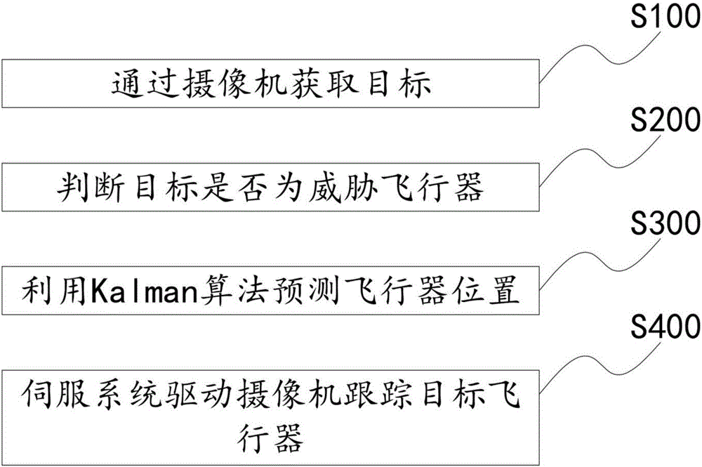
In the special field of anti-drone, the traditional detection and tracking technology cannot meet the needs of anti-drone technology due to the lag of tracking and the technical limitations of being unable to pre-determine the next moment of the target.

Method used


Image

  • Optical tracking system for achieving high-speed tracking and control method thereof
  • Optical tracking system for achieving high-speed tracking and control method thereof

Examples


Embodiment 1

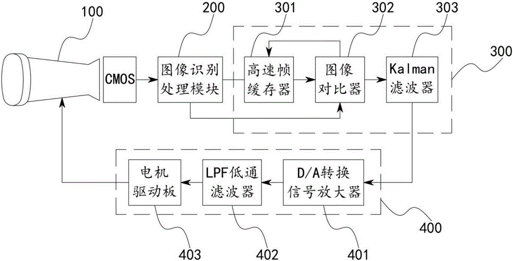
[0048] Such as figure 1 As shown, an optical tracking system for realizing high-speed tracking includes a camera 100 with an optical lens, an image recognition processing module 200, a main controller 300 and a servo system 400 for controlling the movement of the camera; the signal output end of the camera 100 is connected to the The signal input end of the image recognition processing module 200, the signal output end of the image recognition processing module 200 is connected to the signal input end of the main controller 300, and the signal output end of the main controller 300 is connected to the servo system 400 signal input terminal.

Embodiment 2

[0050] This embodiment is on the basis of embodiment 1:

[0051] The camera 100 is a thermal imaging camera with a built-in high-definition CMOS imaging system.

Embodiment 3

[0053] This embodiment is on the basis of embodiment 1:

[0054] The camera 100 is a thermal imaging camera with a built-in high-definition COMS imaging system;

[0055] The camera 100 is a high-definition camera with an image sensor size of 1 / 2in, an image resolution of 1080p, and an effective pixel of 2000W.


PUM


Abstract

The invention discloses an optical tracking system for achieving high-speed tracking. The system comprises a camera with an optical lens, an image recognition processing module, a master controller and a servo system for controlling movement of the camera. The signal output end of the camera is connected with the signal input end of the image recognition processing module, the signal output end of the image recognition processing module is connected with the signal input end of the master controller, and the signal output end of the master controller is connected with the signal input end of the servo system. The invention further discloses a control method of the optical tracking system for achieving high-speed tracking.

Description

technical field [0001] The invention belongs to the technical field of anti-drone, and in particular relates to an optical tracking system for realizing high-speed tracking and a control method thereof. Background technique [0002] With the emergence of new drones, accidents related to drones are constantly coming into people's field of vision, and accidents using drones are no longer uncommon. Uncontrolled drones fell on pedestrians or objects; amateur drone operators flew drones into no-fly zones, drones interfered with civil aviation flights, and interfered with firefighting operations. As a result, the anti-drone system also came into being during the booming development of the drone industry. [0003] The first and main technology in the anti-drone technology system is detection and tracking. Most of the traditional detection and tracking technologies are to obtain target images, and track the target position after analyzing the target images. In the special field of...

Claims


Application Information

Patent Timeline
Patent Type & Authority Applications(China)
IPC IPC(8): G06K9/00G06K9/62G06T7/20
CPCG06T2207/30241G06T2207/30232G06T2207/10016G06V20/46G06F18/22
Inventor 蔡茂杨钦
Owner TELECAST TECH CORP
Learn More