
Oil and gas recovery monitoring device

A monitoring device, oil and gas technology, applied in the direction of distribution device, special distribution device, liquid distribution, transportation or transfer device, etc., can solve the problem of automatic collection of inspection and test data, automatic generation of inspection report, complicated process, and influence on the accuracy of inspection and testing , Objectivity and scientificity and other issues, to achieve the effect of improving monitoring efficiency and scientific level, and accurate detection results

Inactive Publication Date: 2016-11-23
LIAONING UNIVERSITY OF PETROLEUM AND CHEMICAL TECHNOLOGY
View PDF1 Cites 2 Cited by
  • Summary
  • Abstract
  • Description
  • Claims
  • Application Information

AI Technical Summary

Problems solved by technology

[0002] The traditional oil and gas recovery indicator monitoring method usually uses special monitoring instruments for on-site monitoring. After the monitoring is completed, the value is recorded and then reported to the regulatory department. The degree is low, the process is complicated and the monitoring period is long, and it is impossible to realize the automatic collection, analysis, recording and automatic generation of inspection reports of inspection and test data, which not only affects the accuracy, objectivity and scientific nature of inspection and testing, but also lowers work efficiency , and requires the operator to have a certain professional quality
At the same time, all data can only be displayed independently, with poor visibility

Method used


Image

  • Oil and gas recovery monitoring device

Examples


Embodiment Construction

[0032] In order to make the objects and advantages of the present invention clearer, the present invention will be further described in detail below in conjunction with the examples. It should be understood that the specific embodiments described here are only used to explain the present invention, not to limit the present invention.

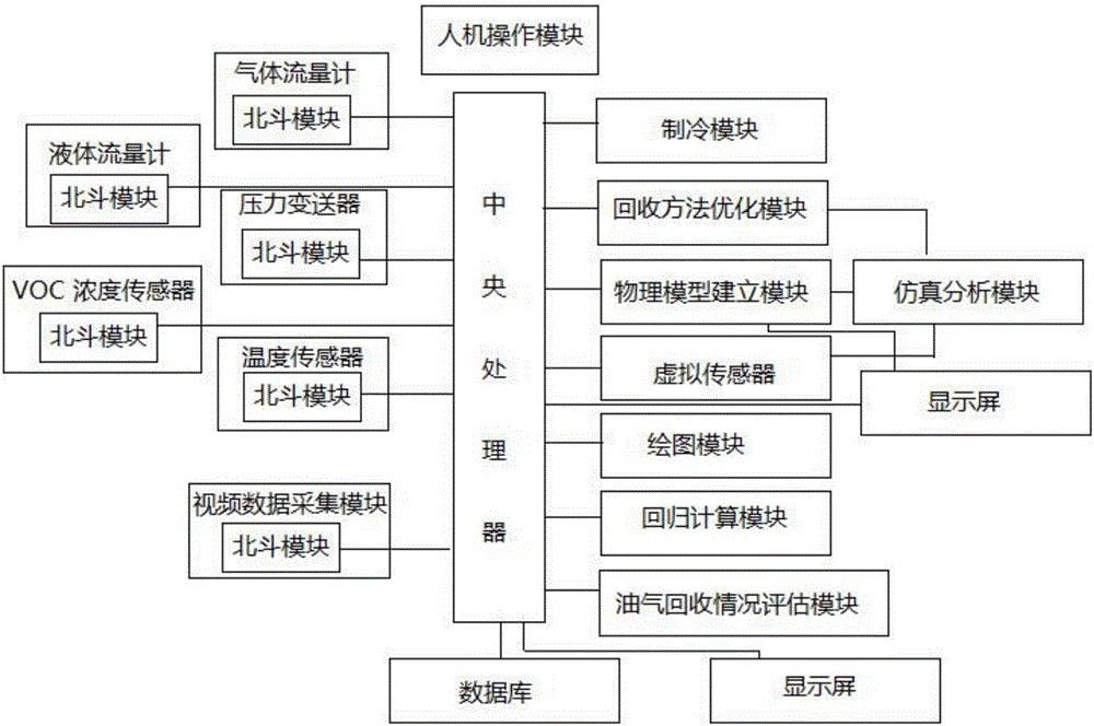
[0033] Such as figure 1 As shown, the embodiment of the present invention provides a kind of oil gas recovery monitoring device, including

[0034] The man-machine operation module is used to input the basic information of the oil and gas recovery pipeline to be monitored, and is also used to input data calling commands and various control commands;

[0035] A number of gas flowmeters are installed at different positions on the return gas pipeline of the secondary recovery device of the tanker to monitor the flow on the gas return pipeline, and send the monitored data to the central processing unit, drawing module and oil and gas recovery throu...


PUM


Abstract

The invention discloses an oil and gas recovery monitoring device. The oil and gas recovery monitoring device comprises a man-machine operation module, a plurality of gas flow meters, a liquid flow meter, a plurality of temperature sensors, a plurality of pressure transmitters, a VOC concentration sensor, a refrigeration module, a video data acquisition module, a central processor, a physical model building module, a recovery method optimization module, a virtual sensor, a simulation analysis module, a drawing module, a regression calculation module and an oil and gas recovery condition evaluation module. With the oil and gas recovery monitoring device of the invention adopted, data automatic acquisition, analysis and automatic generation of records are realized, oil and gas recovery monitoring can be automated and informationized, and detection results are accurate; three-dimensional simulation display of oil and gas recovery to be monitored can be realized through a physical model, so that a user can more intuitively understand the condition of the oil and gas recovery to be monitored; and through the self-definition of the recovery method optimization module, the simulation analysis module and the virtual sensor, the simulation analysis of the physical model can be realized, and the formulation of various measures for different situations can be facilitated.

Description

technical field [0001] The invention relates to the field of oil and gas recovery, in particular to an oil and gas recovery monitoring device. Background technique [0002] The traditional oil and gas recovery indicator monitoring method usually uses special monitoring instruments for on-site monitoring. After the monitoring is completed, the value is recorded and then reported to the regulatory department. The degree is low, the process is complicated and the monitoring period is long, and it is impossible to realize the automatic collection, analysis, recording and automatic generation of inspection reports of inspection and test data, which not only affects the accuracy, objectivity and scientific nature of inspection and testing, but also lowers work efficiency , and requires operators to have certain professional qualities. At the same time, all data can only be displayed independently, and the visibility is poor. Contents of the invention [0003] In order to solve...

Claims


Application Information

Patent Timeline
Patent Type & Authority Applications(China)
IPC IPC(8): G06Q10/04G06Q10/06G06F17/50G06T3/40G06F17/30B67D7/06B67D7/32B67D7/56
CPCB67D7/06B67D7/3281B67D7/56B67D2007/329G06F16/90G06F16/9038G06F30/367G06Q10/04G06Q10/0639G06T3/4038
Inventor 王国付王惠秋王敬壹
Owner LIAONING UNIVERSITY OF PETROLEUM AND CHEMICAL TECHNOLOGY
Learn More