Stator retainer, motor stator and motor stator injection molding method

A retainer and stator technology, which is applied in the manufacture of motor generators, electrical components, electromechanical devices, etc., can solve problems such as stator copper exposure that cannot be injected into the stator, and achieve the effect of preventing injection molding from shifting and avoiding copper exposure

Active Publication Date: 2016-11-23
GREE ELECTRIC APPLIANCES INC +1
View PDF4 Cites 2 Cited by
  • Summary
  • Abstract
  • Description
  • Claims
  • Application Information

AI Technical Summary

Problems solved by technology

[0004] In the embodiment of the present invention, a stator retainer, a motor stator and a motor stator injection molding method are provided to solve the problem in the prior art that the stator cannot be produced in one flow, and the injection molded stator exposes copper

Method used


Image

  • Stator retainer, motor stator and motor stator injection molding method
  • Stator retainer, motor stator and motor stator injection molding method
  • Stator retainer, motor stator and motor stator injection molding method

Examples


Embodiment Construction

[0027] The present invention will be described in further detail below in conjunction with the accompanying drawings and specific embodiments, but not as a limitation of the present invention.

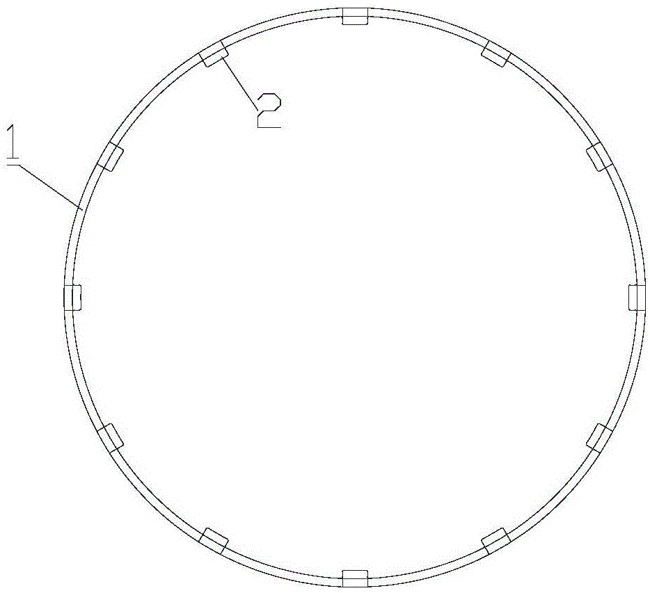
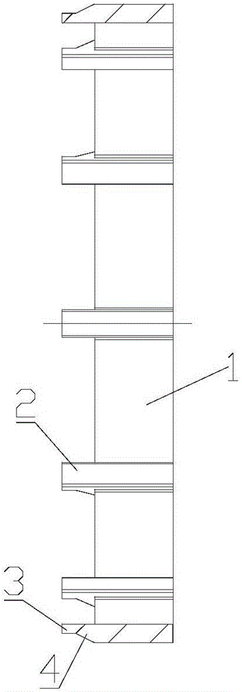
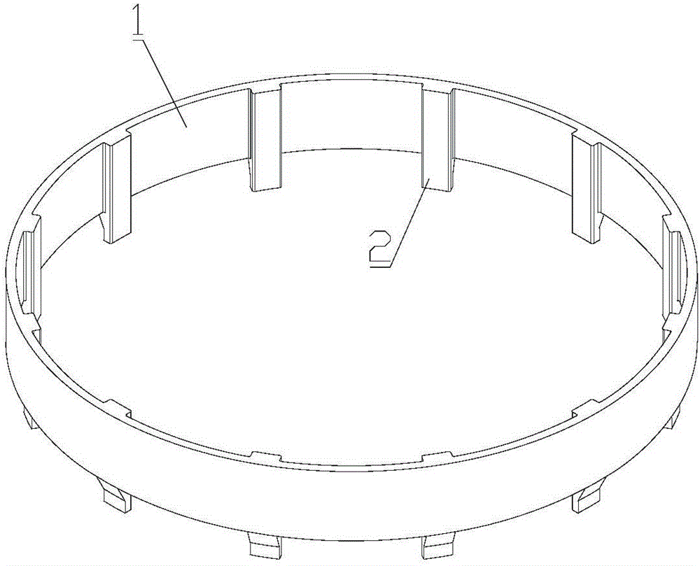
[0028] Please refer to Figure 1 to Figure 7 , the present invention provides a stator holder, which includes a ring body 1 . The outer diameter of the ring body 1 matches the inner diameter of the winding of the stator to be injected, so as to be in contact with the inner wall of the winding during use. Preferably, the stator holder in the present invention can be made of nylon 66 material and 30% glass fiber, which not only increases flexibility, but also has higher rigidity, heat resistance and wear resistance.

[0029] Before injection molding, the stator retainer of the present invention is loaded into the stator coil, so that during the injection molding process, the ring body 1 can not only prevent the winding from being displaced and abnormally deformed, but also avoid the win...


PUM


Abstract

The invention discloses a stator retainer, a motor stator and a motor stator injection molding method. The stator retainer comprises a ring body which is matched with an internal diameter of a winding of a stator to be injected. Because the ring body is in contact with an inner wall of the winding during the injection molding, the injection molding shifting and deformation abnormities of the winding in the injection molding process can be avoided, and the copper exposed problem of injection molding stator can be avoided too. Thus the stator can be finally assembled in one flow production, and the purpose of downsizing for efficiency is reached.

Description

technical field [0001] The invention relates to the field of stator manufacturing, in particular to a stator holder, a motor stator and an injection molding method for the motor stator. Background technique [0002] In the prior art, the production process of the stator of the iron-cased plastic-sealed motor is cumbersome, including stator embedding, stator varnish dipping, stator cooling, stator injection molding, etc., requiring a large number of operators. Production. In addition, in this process, the stator needs to be dipped in paint. The purpose is to increase the withstand voltage level of the stator winding and the hardness of the winding, and prevent the winding from being displaced and deformed by the BMC molding compound during the injection molding process of the stator. Stator injection molding. [0003] However, when the stator is dipped in paint, the diameter of the stator winding will rebound during the dipping process of the stator (that is, the inner diam...

Claims


Application Information

Patent Timeline
Patent Type & Authority Applications(China)
IPC IPC(8): H02K1/18H02K15/12B29C45/14
CPCB29C45/14065B29C45/14819H02K1/18H02K15/12
Inventor 李佳毅袁启毅管文龙陈生凤陈东锁
Owner GREE ELECTRIC APPLIANCES INC
Why Eureka
Try Eureka