
Position adjusting mechanism for taping machine clamping mechanism

A technology of adjusting mechanism and clamping mechanism, which is applied in the direction of electromechanical devices, manufacturing motor generators, electrical components, etc., can solve the problems of reducing the service life of devices, high labor costs, and low work efficiency, so as to prolong the service life and reduce labor costs. The effect of high and low work efficiency

Active Publication Date: 2016-11-23
温州市桑德拉自动化科技有限公司
View PDF6 Cites 3 Cited by
  • Summary
  • Abstract
  • Description
  • Claims
  • Application Information

AI Technical Summary

Problems solved by technology

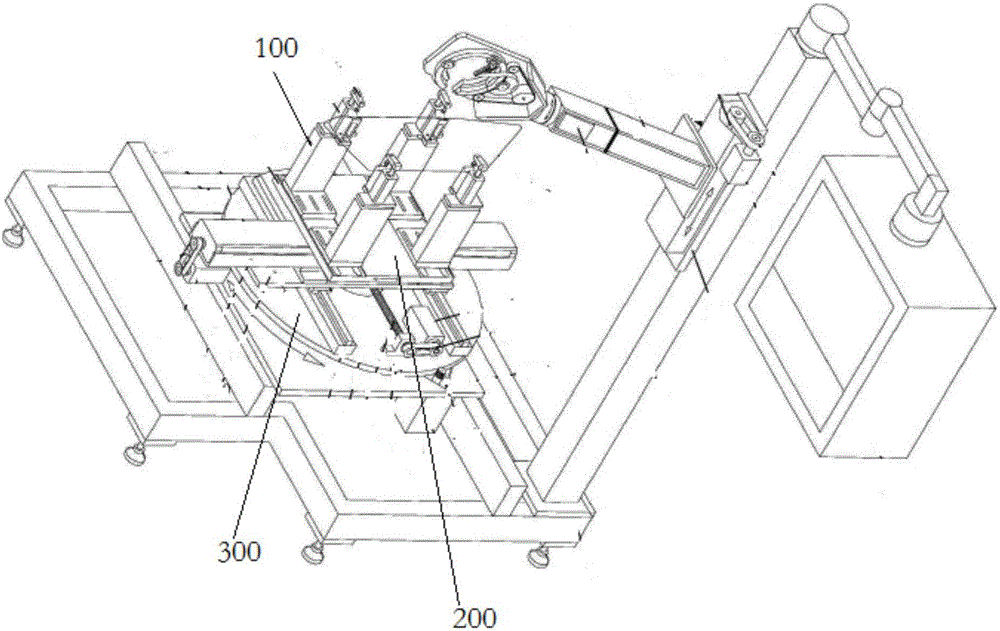
In this taping machine, the support plate 200 is an inseparable whole, on which there are multiple installation positions of the clamping mechanism 100. According to the structure and size of the coil to be taped, the clamping mechanism selects different installation positions for fixing. on the support plate 200, but when replacing a coil of another size, it is necessary to disassemble the clamping mechanism 100 on the support plate 100 first, and then adjust the position of the clamping mechanism 100 according to the size of the coil. The installation position on the support plate 200 is fixed, and then the clamping mechanism 100 is reinstalled and fixed, resulting in low work efficiency and high labor costs. At the same time, repeated disassembly and installation of device components may damage the device and reduce the service life of the device.

Method used


Image

  • Position adjusting mechanism for taping machine clamping mechanism
  • Position adjusting mechanism for taping machine clamping mechanism
  • Position adjusting mechanism for taping machine clamping mechanism

Examples


Embodiment Construction

[0043] The technical solutions of the present invention will be clearly and completely described below in conjunction with the accompanying drawings. Apparently, the described embodiments are some of the embodiments of the present invention, but not all of them. Based on the embodiments of the present invention, all other embodiments obtained by persons of ordinary skill in the art without making creative efforts belong to the protection scope of the present invention.

[0044] In the description of the present invention, it should be noted that the terms "center", "upper", "lower", "left", "right", "vertical", "horizontal", "inner", "outer" etc. The indicated orientation or positional relationship is based on the orientation or positional relationship shown in the drawings, and is only for the convenience of describing the present invention and simplifying the description, rather than indicating or implying that the referred device or element must have a specific orientation, ...


PUM


Abstract

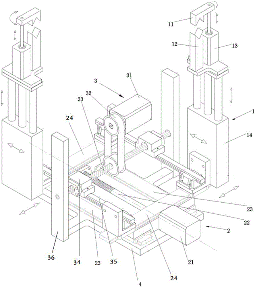
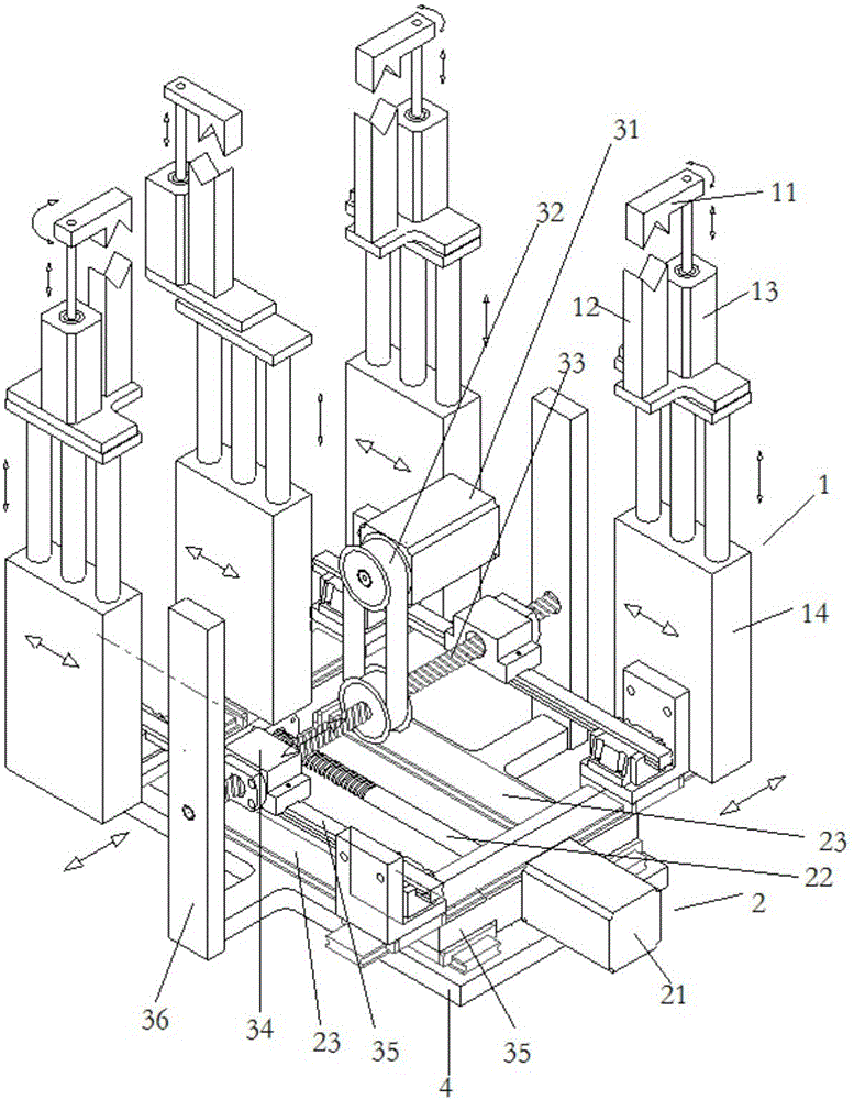
The invention discloses a position adjusting mechanism for a taping machine clamping mechanism. The clamping mechanism comprises a plurality of clamping units arranged according to a coil contour. The plurality of clamping units form a clamping contour adapted to the coil contour. The position adjusting mechanism is connected between the plurality of the clamping units. The plurality of clamping units can be driven to generate relative shift through the adjustment of the position adjusting mechanism, and thus the clamping contour formed by the plurality of clamping units is changed. The position adjusting mechanism connected between the clamping units can effectively avoid the trouble, and the relative position between the clamping units can be adjusted through buttons on an operation panel of a taping machine according to the coil contours with different sizes so as to be adapted to the coil without dismounting the clamping units. The operation is simple and fast. The work efficiency is greatly improved. The artificial cost is reduced, and the equipment service life is prolonged.

Description

technical field [0001] The invention relates to the technical field of coil production machinery and equipment, in particular to a position adjustment mechanism for a clamping mechanism of a taping machine. Background technique [0002] With the development of society, the demand for coils in the motor field is also increasing, and the structure of the coils is also becoming more and more complicated due to the needs of use. The coil body needs to be wrapped with a layer of insulating tape when it is used later. In the past, the insulating tape was wound by hand. There are disadvantages of difficult winding, low winding precision, and low efficiency. Coils of different shapes or angles increase the difficulty of winding, and the increasing labor costs for enterprises will greatly increase the overall production cost. [0003] In order to solve the above problems, the applicant submitted an invention patent application to the State Intellectual Property Office on August 13, 2...

Claims


Application Information

Patent Timeline
IPC IPC(8): H02K15/04
CPCH02K15/0435
Inventor 李金光黄祥志
Owner 温州市桑德拉自动化科技有限公司
Learn More