Phase lock loop circuit and signal frequency adjusting method therefor

A phase-locked loop and frequency adjustment technology, which is applied in the direction of electrical components and power automatic control, can solve the problems of poor tolerance of the phase-locked loop and difficulty in locking the output signal of the phase-locked loop.

Inactive Publication Date: 2016-11-23
ALICORP
View PDF8 Cites 0 Cited by
  • Summary
  • Abstract
  • Description
  • Claims
  • Application Information

AI Technical Summary

Problems solved by technology

[0003] However, when the VCO gain is greatly reduced, the tolerance of the phase-locked loop is easily deteriorated, and the phase-locked loop is easily affected by the variation of the circuit process and it is difficult to lock the frequency of the output signal.

Method used


Image

  • Phase lock loop circuit and signal frequency adjusting method therefor
  • Phase lock loop circuit and signal frequency adjusting method therefor
  • Phase lock loop circuit and signal frequency adjusting method therefor

Examples


Embodiment Construction

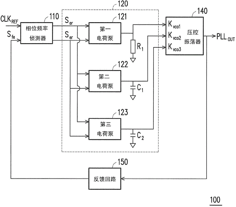
[0048] Please refer to figure 1 , figure 1 A schematic circuit block diagram of a phase-locked loop circuit 100 according to a related example of the present invention is shown. The PLL circuit 100 has a phase frequency detector 110 , a frequency control circuit 120 , a voltage controlled oscillator 140 and a feedback loop 150 . The phase frequency detector 100 receives an input reference signal CLK REF and the feedback signal S fe , and accordingly output the error signal S er . The frequency control circuit 120 can adjust the signal output to the voltage-controlled oscillator 140 to adjust the oscillation signal PLL output by the phase-locked frequency circuit 100 OUT . Further, the frequency detector 120 has a first charge pump (charge pump) 121 , a second charge pump 122 and a third charge pump 123 , and are respectively connected to the resistor R1 , the capacitor C1 and the capacitor C2 . The voltage-controlled oscillator can adjust the signal K according to the v...


PUM


Abstract

Provided is a phase lock loop circuit, which comprises a phase frequency detector, a frequency control circuit, a digital control circuit and a voltage controlled oscillator. The phase frequency detector generates an error signal according to an input reference signal and a feedback signal, wherein the feedback signal is generated based on an oscillating signal. The frequency control circuit is coupled with the phase frequency detector, and receives the error signal to generate a frequency adjusting signal. The digital control circuit is coupled with the phase frequency detector, and receives the error signal to generate a digital counting signal. The voltage controlled oscillator is coupled with the frequency control circuit and the digital control circuit, and generates the oscillating signal on the basis of the frequency adjusting signal and the digital counting signal.

Description

technical field [0001] The present invention relates to a phase-locked loop circuit, and in particular to a phase-locked loop circuit and a signal frequency adjustment method thereof. Background technique [0002] In the integrated circuit design of a phase lock loop (PLL), capacitors are often the components that occupy the largest circuit area. Therefore, if the circuit area of ​​the PLL is to be reduced, it is necessary to solve the problem of capacitor space in the circuit. Generally speaking, the solution to the above problems can be to move the capacitor to the outside of the integrated circuit, and connect it to the external capacitor on the PCB board by adding an integrated circuit pin, but this method will increase the efficiency of the circuit. Design cost. Another solution is to reduce the gain (gain) of the voltage controlled oscillator (VCO) in the phase-locked loop, thereby reducing the capacitor requirement and reducing the area. [0003] However, if the VC...

Claims


Application Information

Patent Timeline
Patent Type & Authority Applications(China)
IPC IPC(8): H03L7/099
Inventor 宋厚宽庄志禹
Owner ALICORP
Why Eureka
Try Eureka