
Loaders with booster cylinders

A loader and oil cylinder technology, which is applied to mechanically driven excavators/dredgers, earth movers/shovels, construction, etc., can solve problems such as the difficulty of increasing breakout force, improve bucket full rate, and facilitate layout , the effect of increasing productivity

Active Publication Date: 2018-09-11
GUANGXI LIUGONG MASCH CO LTD
View PDF4 Cites 0 Cited by
  • Summary
  • Abstract
  • Description
  • Claims
  • Application Information

AI Technical Summary

Problems solved by technology

[0003] The technical problem to be solved by the present invention is to provide a loader with a booster cylinder to increase the breakout force in view of the difficulty in increasing the breakout force of the existing loader without changing other parameters

Method used


Image

  • Loaders with booster cylinders
  • Loaders with booster cylinders
  • Loaders with booster cylinders

Examples


Embodiment Construction

[0027] The specific implementation will be described below in conjunction with the accompanying drawings.

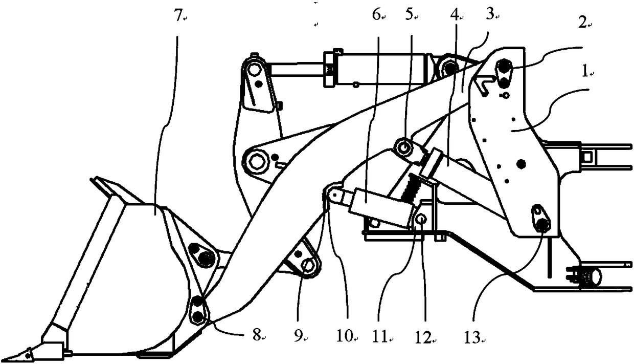
[0028] like figure 1 As shown, the loader in this embodiment includes a vehicle frame 1, a boom 3, a hydraulic system, and a booster cylinder 6. The rear end of the boom 3 is hinged to the frame 1 through the rear hinge shaft 2 of the boom, and the front end is articulated through the boom shaft 2. The front hinge shaft 8 is hinged to the bucket 7, and the two ends of the boom cylinder 4 in the hydraulic system are respectively hinged between the boom 3 and the vehicle frame 1, wherein the front end of the boom cylinder 4 is connected to the front hinge shaft 5 of the boom cylinder through the boom cylinder 4. The boom 3 is hinged, the rear end of the boom cylinder 4 is hinged with the vehicle frame 1 through the rear hinge shaft 13 of the boom cylinder, and the telescopic lifting boom 3 of the boom cylinder 4 rotates around the hinge point at the rear end of the boom. ...


PUM


Abstract

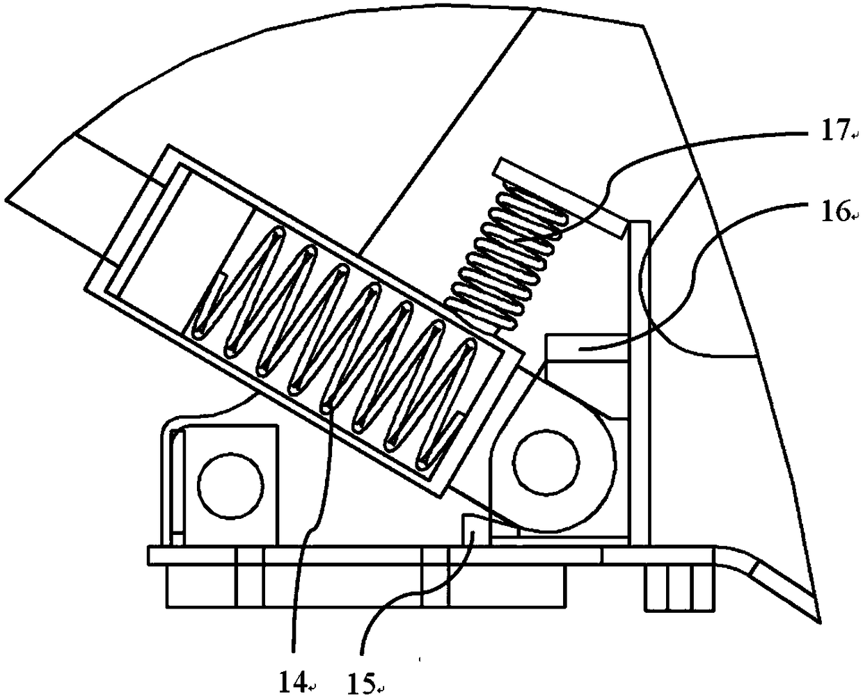
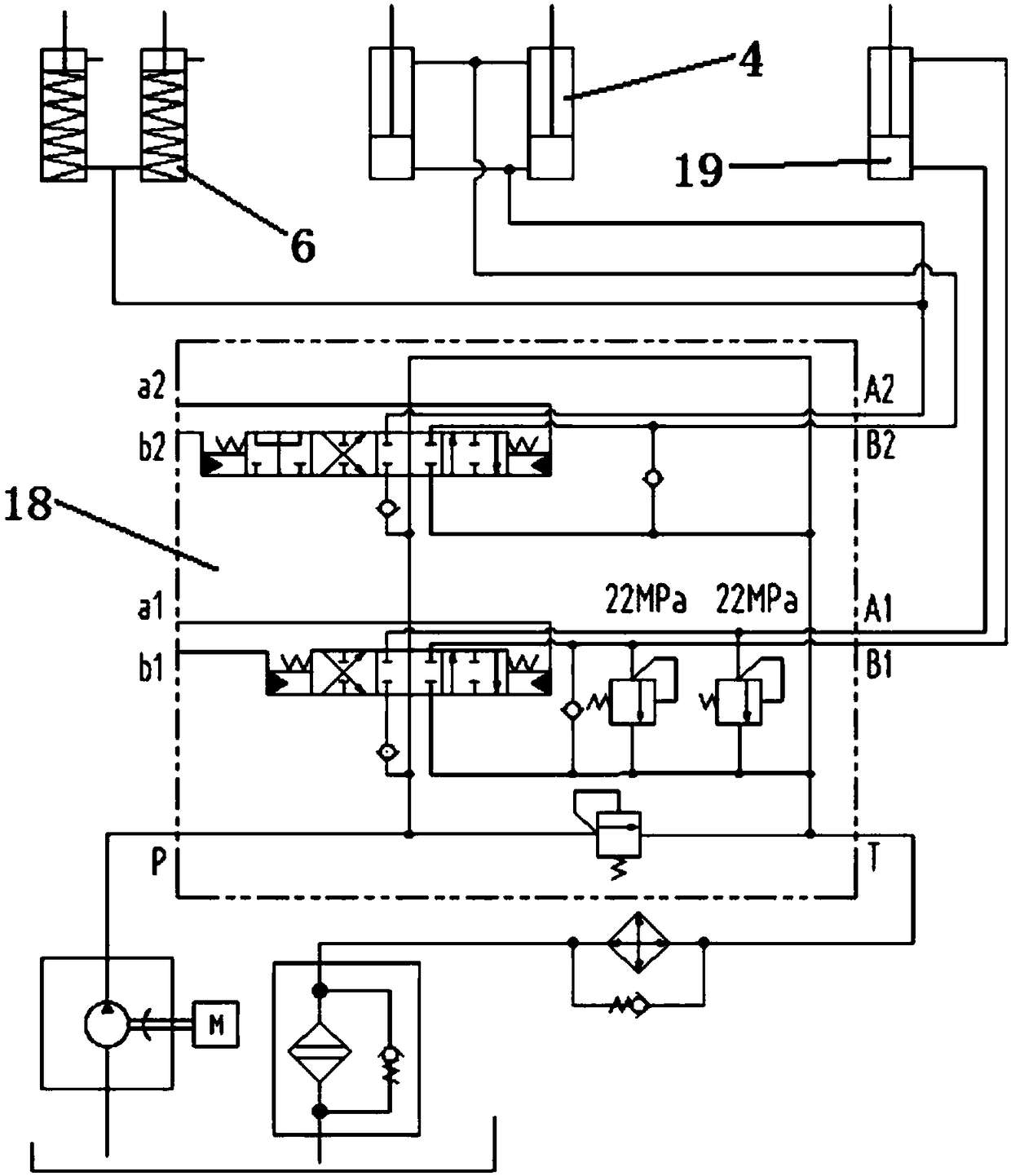
The present invention relates to a loader, which solves the problem that the existing loader is difficult to increase the digging force without changing other parameters. The present invention provides a loader comprising a frame, a movable arm, a hydraulic system and a booster cylinder. The rear end of the movable arm is hinged to the frame, two ends of the movable arm cylinder in the hydraulic system are hinged between the movable arm and the frame, a telescopic lifting arm of the movable arm cylinder rotates around the hinged point of the rear end of the movable arm, the booster cylinder is located in front of the movable arm cylinder, the hinged end of the rear portion of the booster cylinder is hinged to the frame, and the other end obliquely points to the free end ahead, the movable arm is provided with a booster carrying portion corresponding to the free end of the booster cylinder, and the booster carrying portion and the free end of the booster cylinder are in a meshing connection that can be automatically disengaged. In the present invention, the booster cylinder and the movable arm cylinder act together on the movable arm to increase the load of the loader. The booster carrying portion of the movable arm is disengaged from the booster cylinder, and the movable is lifted by the boom cylinder alone.

Description

technical field [0001] The present invention relates to a loader, more particularly, relates to a loader with a booster cylinder. Background technique [0002] At present, in the matching of the design of the whole loader, the breakout force of the boom, the lifting force of the boom, the lifting height and the lifting time are the key parameters of the whole machine, which need to be considered in the design. Typically, the boom breakout force of a loader is much greater than the boom lift force. The size of the breakout force of the boom seriously affects the full bucket rate of the bucket, thereby affecting the productivity of the loader, and further affects the energy consumption of the loader; the lifting capacity of the boom affects the lifting force and lifting time of the working device , thereby affecting the productivity of the loader. Due to the influence of the structural arrangement of the working device and the need to take into account the above parameters, ...

Claims


Application Information

Patent Timeline
Patent Type & Authority Patents(China)
IPC IPC(8): E02F3/28E02F3/42
CPCE02F3/28E02F3/427
Inventor 莫德志
Owner GUANGXI LIUGONG MASCH CO LTD
Learn More