
Car light spiral optical guide tooth

A technology of light guide teeth and spiral shape, which is applied in the processing and processing of vehicle light conductors, can solve the problems of light energy loss, low efficiency, and insufficient vision, and achieves the effect of improving input energy and improving use efficiency.

Inactive Publication Date: 2016-11-30
HASCO VISION TECHNOLOGY CO LTD
View PDF11 Cites 1 Cited by
  • Summary
  • Abstract
  • Description
  • Claims
  • Application Information

AI Technical Summary

Problems solved by technology

As a result, the visual is obviously not full enough
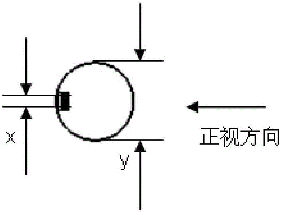
[0007] In terms of luminous efficiency, traditional light guide teeth usually only have one row of light guide teeth, and the efficiency is relatively low, resulting in a lot of direct loss of light energy
[0008] like figure 2 As shown, since there is only one row of light guide teeth, the input and output of the light source have only one direction, and thus, the entire light guide only uses a part of the light guide surface

Method used


Image

  • Car light spiral optical guide tooth
  • Car light spiral optical guide tooth
  • Car light spiral optical guide tooth

Examples


Embodiment 1

[0035] The invention relates to a spiral light guide tooth for a car lamp. The light guide tooth is arranged on the whole circumference of the strip light guide body, and the light guide tooth covers the periphery of the strip light guide body in a spiral shape. The diameter of the light guide is 5-10mm.

[0036] The distance between the light guide teeth spirally covering the periphery of the bar-shaped light guide body is 0.5-2 mm, and the height of the light guide teeth is 0.3-1 mm.

[0037] In addition, the installation inclination of the light guide teeth covering the periphery of the bar-shaped light guide body in a spiral shape is 15-45 degrees.

[0038] The material of the optical guide tooth is PC or PMMA.

[0039] The angle R of the tips of the light-guiding teeth covering the periphery of the bar-shaped light-guiding body in a spiral shape is 0.04-0.07.

Embodiment 2

[0041] Except for the following differences, others are the same as in Example 1, and a spiral light guide tooth for a car lamp of the present invention is obtained:

[0042] Light-guiding teeth are arranged around the entire circumference of the strip-shaped light-guiding body, and the light-guiding teeth cover the periphery of the strip-shaped light-guiding body in a spiral shape. The diameter of the light guide is 5-10mm.

[0043] The distance between the light guide teeth spirally covering the periphery of the bar-shaped light guide body is 0.5-2 mm, and the height of the light guide teeth is 0.3-1 mm.

[0044] In addition, the installation inclination of the light guide teeth covering the periphery of the bar-shaped light guide body in a spiral shape is 15-45 degrees.

[0045] The angle R of the tips of the light-guiding teeth covering the periphery of the bar-shaped light-guiding body in a spiral shape is 0.04-0.07.

[0046] According to the spiral light guide tooth fo...


PUM

PropertyMeasurementUnit
Diameteraaaaaaaaaa

Abstract

Provided is a car light spiral optical guide tooth which is arranged on a bar-shaped optical conductor. The car light spiral optical guide tooth is characterized in that the optical guide teeth are arranged on the periphery of the bar-shaped optical conductor and spirally cover the periphery of the bar-shaped optical conductor, the spacing of the optical guide teeth spirally cover the periphery of the bar-shaped optical conductor is in the range of 0.5-2mm, and the height of the optical guide teeth is in the range of 0.3-1mm. According the full-periphery optical guide teeth design, the whole optical guide surface is completely enveloped, the light guide is maximally utilized, the 'full input and full output' can be realized by the same one light source, so that the use efficiency of the whole light guide is improved.

Description

technical field [0001] The invention relates to the processing of a car light conductor and a processing method thereof, in particular, the invention relates to a spiral light guide tooth for a car light. The spiral light-guiding tooth for a car light is a light-guiding strip used for a car rear light and the like, and can be applied to various light sources. According to the spiral light guide tooth for vehicle lamps of the present invention, the highlight range of the light guide can be increased to the greatest extent, the visual fullness can be increased, and the use efficiency of the entire light guide can be improved by utilizing the light guide to the greatest extent. When the light source is constant, the input energy of the spiral light guide tooth design can be significantly improved compared with the single light guide tooth. technical background [0002] The light guide gear used for car lights is a strip-shaped light guide body, one side of which is basically a...

Claims


Application Information

Patent Timeline
IPC IPC(8): F21V7/10F21V8/00G02B6/00
CPCF21V7/10G02B6/0038F21V2200/00F21S43/237
Inventor 沈海军孙良柱高辉严彬华
Owner HASCO VISION TECHNOLOGY CO LTD
Learn More