
S-shaped acceleration and deceleration control method for changing speed and position of object on line

A technology of acceleration and deceleration control and target speed, applied in digital control, program control, electrical program control, etc., can solve problems such as complex algorithms, vibration and noise, and discontinuous acceleration curves

Active Publication Date: 2016-11-30
SOUTH CHINA UNIV OF TECH
View PDF4 Cites 88 Cited by
  • Summary
  • Abstract
  • Description
  • Claims
  • Application Information

AI Technical Summary

Problems solved by technology

The T-type acceleration and deceleration algorithm has the advantages of simple algorithm, short time consumption and easy implementation, but the acceleration curve is discontinuous, there is a sudden change in speed, and various vibrations and noises are prone to occur. There is a flexible impact in the machine tool movement, and it is suitable for applications that do not require high movement accuracy. low-speed, low-cost CNC system
The smoothness of the exponential acceleration and deceleration algorithm is better than that of the T-shaped acceleration and deceleration algorithm, and the motion accuracy is high, but the algorithm is complex, the calculation takes a long time, the acceleration and deceleration starting point and end point have sudden changes in acceleration and deceleration, and there is also a flexible impact
The trigonometric function acceleration and deceleration rules can realize smooth motion, but due to the complex calculation of trigonometric functions, it cannot meet the real-time requirements of the numerical control system. It must be processed in advance, stored in the memory as a table, and realized by looking up the table. ;In addition, the current trigonometric function acceleration and deceleration cannot fully utilize the advantages of the jerk and the maximum allowable value of the acceleration in order to ensure the speed line shape, resulting in that the speed cannot reach the expected value in a relatively short time and distance
The traditional S-shaped acceleration and deceleration algorithm also has problems such as complex calculation formulas, time-consuming prediction and calculation of actual deceleration points, and multi-cycle compensation for remaining distances.

Method used


Image

  • S-shaped acceleration and deceleration control method for changing speed and position of object on line
  • S-shaped acceleration and deceleration control method for changing speed and position of object on line
  • S-shaped acceleration and deceleration control method for changing speed and position of object on line

Examples


Embodiment Construction

[0270] The technical solutions in the embodiments of the present invention will be clearly and completely described below in conjunction with the accompanying drawings in the embodiments of the present invention. Obviously, the described embodiments are only part of the embodiments of the present invention, not all of them. Based on the implementation manners in the present invention, all other implementation manners obtained by persons of ordinary skill in the art without making creative efforts belong to the scope of protection of the present invention.

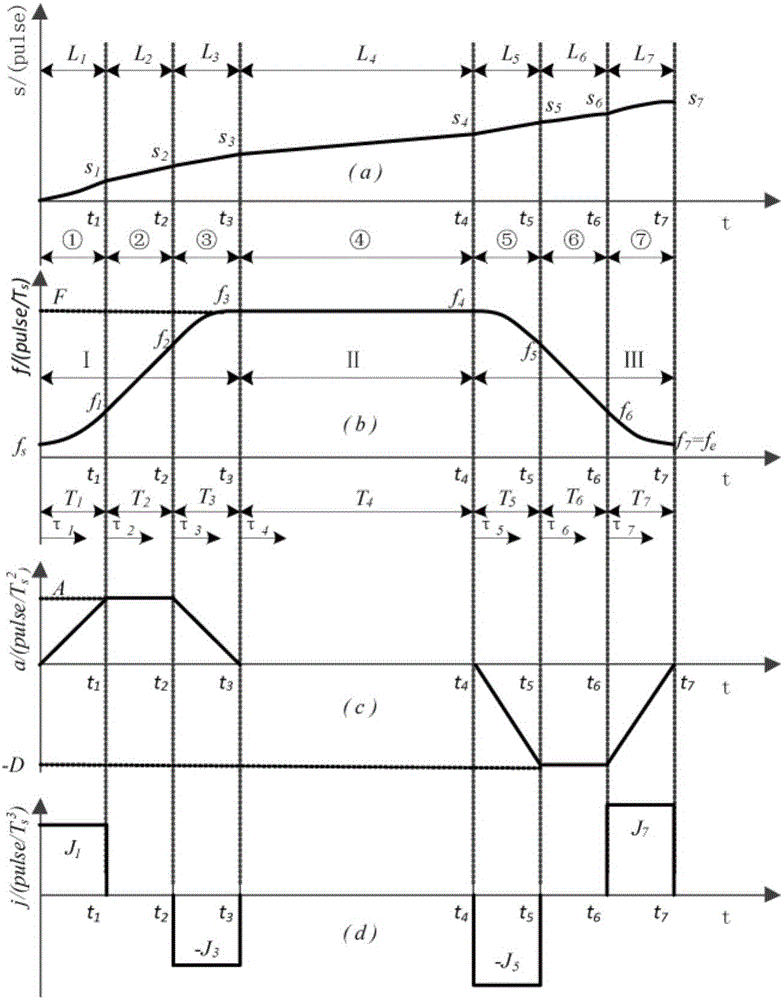
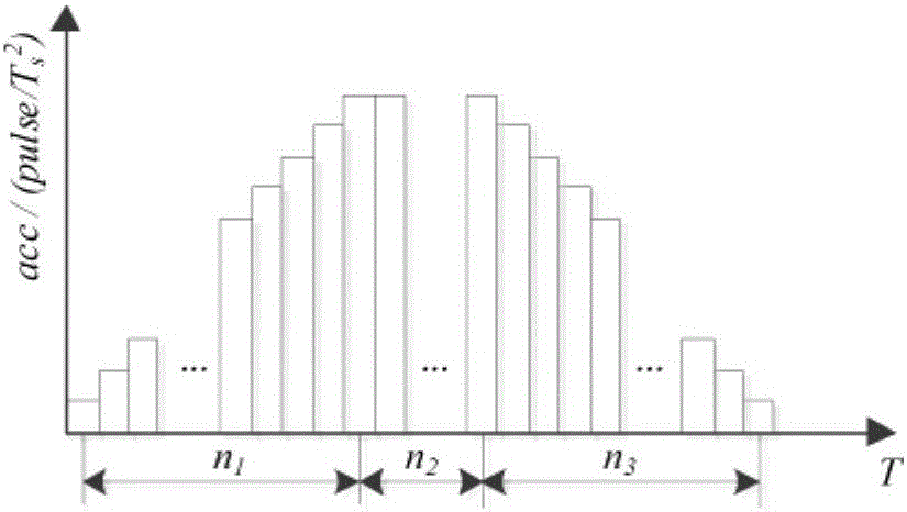
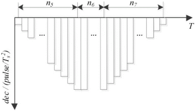
[0271] Such as figure 1 Shown is a schematic diagram of the speed planning of the S-curve acceleration and deceleration control method. The process of the S-shaped acceleration and deceleration control method proposed by the present invention can be divided into acceleration zone I, constant velocity zone II and deceleration zone III. Acceleration zone Ⅰ includes acceleration and acceleration section ①, uniform acceleratio...


PUM


Abstract

The present invention provides an S-shaped acceleration and deceleration control method for changing speed and position of an object on line. The method comprises the acceleration phase speed planning, the deceleration phase speed planning, the constant speed phase speed planning, the real speed reduction point predication, the maximum speed processing, the surplus distance compensation, the online object speed changing algorithm and the online object position changing algorithm. An acceleration and deceleration discretization speed planning method is employed and the user input parameters are combined to calculate the operation time of a seven-phase speed planning phase. It is determined whether the maximum acceleration and the maximum speed can reach the criterion or not, the integration problem of a sampling period Ts according to the acceleration / deceleration acceleration, the acceleration / deceleration speed and the final position L after discretization is considered, and the real reachable acceleration / deceleration acceleration, the acceleration / deceleration speed and the feed rate are corrected. The S-shaped acceleration and deceleration control method for changing speed and position of the object on line greatly simplifies an original calculation formula and saves lots of operation time of a computer, and the surplus distance employs a one-time compensation method in the speed reduction process.

Description

technical field [0001] The invention belongs to the field of motion control, in particular to a method for realizing an S-shaped curve acceleration and deceleration control method of a motion control system. Background technique [0002] Motion control is the key technology for the realization of the CNC system. A good acceleration and deceleration control method can effectively avoid the phenomenon of shock, out of step or vibration in the motion process of the CNC equipment. High-speed and high-precision machining is an important development direction of CNC machining. It not only requires the CNC machine tool to respond quickly and reach the specified speed in a short time; it also requires the movement of the machining process to be as stable as possible and the impact is small. Therefore, on the basis of ensuring the smooth motion of the machine tool, how to realize the optimal acceleration and deceleration control law with the goal of the shortest processing transition...

Claims


Application Information

Patent Timeline
IPC IPC(8): G05B19/4103
CPCG05B19/4103G05B2219/34169
Inventor 李迪吴杰文李松
Owner SOUTH CHINA UNIV OF TECH
Learn More