Transverse movement type rough cutting machine

A rough cutting machine and frame technology, which is applied to harvesters, cutters, agricultural machinery, etc., can solve problems such as unfavorable storage, fixed frame structure, maintenance hazards, etc., so as to facilitate maintenance and replacement, reduce storage area, improve The effect of cutting strength

Inactive Publication Date: 2016-12-07
ZHEJIANG LEKELAI MACHINERY
4 Cites 0 Cited by

AI-Extracted Technical Summary

Problems solved by technology

However, the existing rough cutting machine has the disadvantages of the following aspects: 1. The existing rough cutting machine is relatively large in size and is suitable for weeding in farmland; but its frame structure is fixed and occupies a large space, which is not conducive to storage
Secondly, the cutting parts of this type of rough cutting machine are at the bottom of the frame. If the cutting parts are loose, the rough cutting machine needs to be lifted by the hanger for maint...

Abstract

The invention relates to the field of farm machinery, in particular to a transverse movement type rough cutting machine. The machine comprises a machine frame, a transmission component and a cutting component, wherein the transmission component and the cutting component are arranged on the machine frame, and the machine frame comprises a tension frame assembly, a top frame arranged on the tension frame assembly, and a machine shell assembly connected to the end of the tension frame assembly. The machine is novel in structure; on one hand, the occupied area of the machine can be reduced through folding of the machine frame, so that storage and maintenance are convenient; on the other hand, the cutting component is improved to be adapted to high-strength cutting.

Application Domain

Technology Topic

Image

  • Transverse movement type rough cutting machine
  • Transverse movement type rough cutting machine
  • Transverse movement type rough cutting machine

Examples

  • Experimental program(1)

Example Embodiment

[0018] The preferred embodiments of the present invention will be described in further detail below in conjunction with the accompanying drawings.
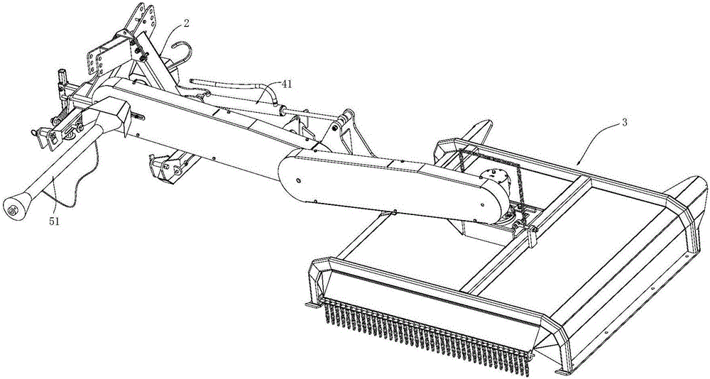
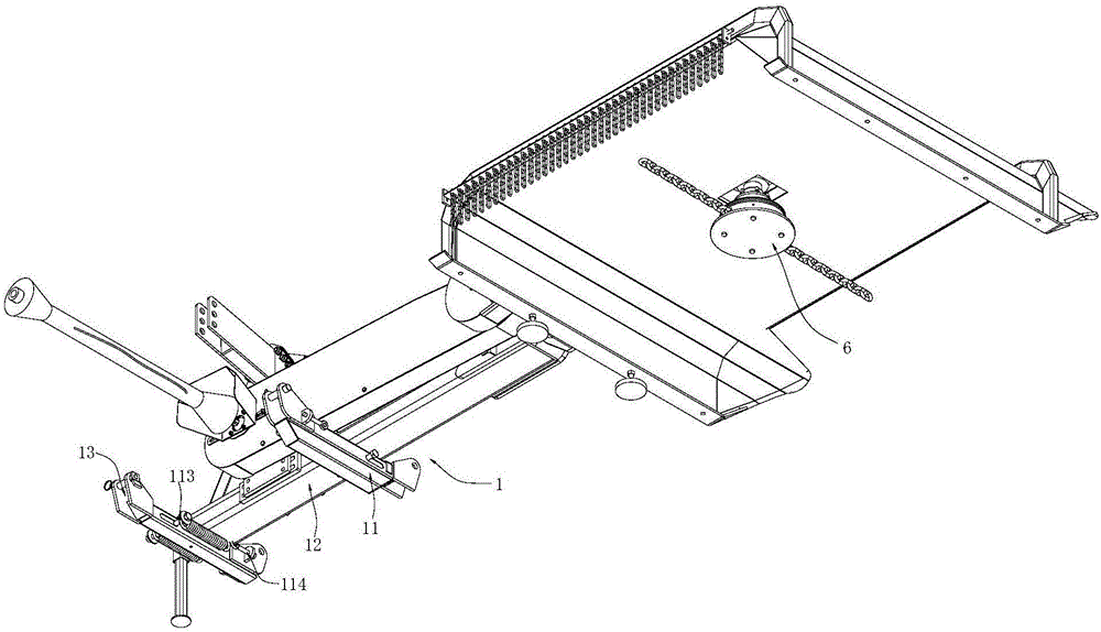
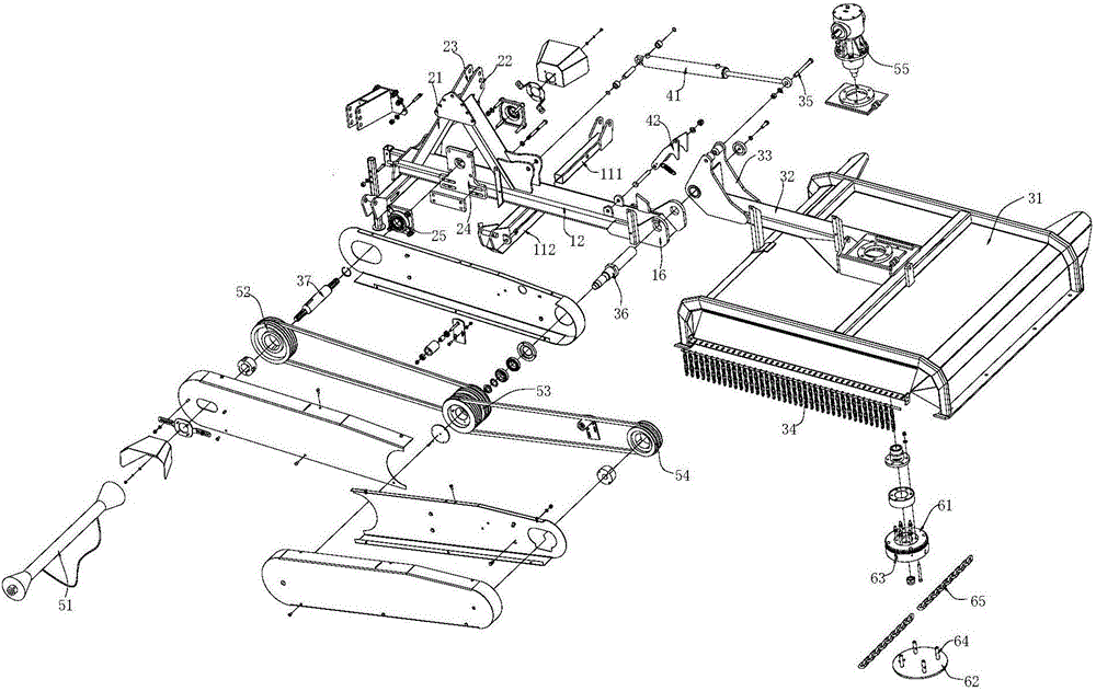
[0019] Such as Figure 1~3 The shown horizontal rough cutting machine includes a frame, and a transmission assembly and a cutting assembly 6 arranged on the frame. The frame includes a pulling frame assembly 1, a top frame 2 arranged on the pulling frame assembly 1, and a casing assembly 3 connected to the end of the pulling frame assembly 1.
[0020] The pull frame assembly 1 includes two sets of pull frame bottom pipes 11 arranged parallel to each other, and a pull frame 12 fixed on the two sets of pull frame bottom pipes 11. The setting direction of the pull frame is perpendicular to the setting direction of the pull frame bottom pipe 11. Both ends of the bottom pipe 11 are provided with lower suspension grooves 13. The bottom tube 11 of the pulling frame includes an inner tube 111 of the pulling frame and a sleeve sleeve 112 connected to the inner tube 111 of the pulling frame. A linear slide groove is provided on the side of the tube body of the inner tube 111 of the pull frame, and a positioning rod 113 is arranged in the linear slide groove. Both ends of the rod body of the positioning rod are located outside the inner tube 111 of the pull frame; A connecting bolt 114 is fixed, and both ends of the rod body of the positioning rod are connected with the connecting bolts on the two side walls through a tension spring. The top frame 2 includes two support frame rods 21 arranged obliquely on the upper end surface of the frame, and two hangers 22 arranged on the support frame rod 21; the upper ends of the two support frame rods 21 are connected to each other, and the two support frames The lower end of the rod 21 is connected and fixed on the pull frame, and a triangular support is formed between the two support rods 21 and the pull frame. Two hangers 22 are respectively fixed on both sides of the connecting ends of the two support frame rods 21, and the hanger 22 is provided with an upper suspension groove 23, which is located between the upper suspension groove 23 and the two lower suspension grooves 13 on the same side of the pull frame Form a three-point suspension structure.
[0021] In the above structure, the horizontal roughing machine is connected to the rear side of the tractor through a three-point suspension structure, which can provide a stable connection structure; and because the connecting part and the cutting part of the horizontal roughing machine are on both sides, the horizontal line When the rough cutting machine is connected to the rear of the tractor, the cutting position of the horizontal rough cutting machine is at the rear of the tractor side; in order to facilitate the flexible use in the actual environment, the opposite sides of the horizontal rough cutting machine are equipped with a set of three-point suspension structure. Just choose one connection, which is very convenient. In addition, when the horizontal rough cutting machine is working, its cutting position is raised relative to the ground. The machine’s focus is on the two pull frame bottom pipes 11. The tension spring structure on the pull frame bottom pipe 11 helps to reduce the vibration generated during the forward movement of the machine, and lift Equipment stability.
[0022] The pull frame is also provided with a storage cylinder 41, a hinge base 16 and a clamping component 42. The cylinder end of the storage cylinder 41 is hinged on the top frame 2, and the hinge base 16 is fixed on the rear end of the pull frame. , The engaging component 42 is hinged on the pull frame on the front side of the hinge base 16, and the engaging component 42 and the pull frame are also connected by a tension spring. The housing assembly 3 includes a housing 31, a connecting frame 32 fixed on the housing 31, and a hinged movable seat 33 fixed on the end of the connecting frame 32. The housing 31 is in a U shape with an opening facing downward. A cutting cavity is formed inside the housing 31, and a plurality of stop chains 34 are hung on the side cavity of the cutting cavity. The hinged movable seat 33 is hinged on the hinge base 16 through a first shaft 36. The hinged movable seat 33 is provided with a clamping shaft 35, and the output shaft end of the receiving cylinder 41 is hinged with the clamping shaft 35. When the storage cylinder 41 drives the hinged movable seat 33 to rotate, the clamping shaft 35 on the hinged movable seat 33 can be clamped with the engaging member 42.
[0023] In the above structure, the drawing frame of the rough cutting machine is provided with a storage cylinder 41, a hinge base 16 and an engaging member 42, and the hinged movable seat 33 of the connecting frame 32 is hinged to the hinge base of the drawing frame through the first shaft 36 16, the output shaft end of the storage cylinder 41 is hinged with the hinged movable seat 33; this structure can realize the relative rotation between the connecting frame 32 and the pull frame through the drive of the storage cylinder 41, so that the rough cutting machine can be The cutting part is lifted; when the storage cylinder 41 drives the hinged movable seat 33 to rotate, the clamping shaft 35 on the hinged movable seat 33 can be clamped with the clamping member 42, and the clamping relationship can provide a firm positioning, and the rough cutting The cutting part of the machine is lifted and fixed for a long time. On the one hand, it can be used for regular storage to reduce the storage area of ​​the rough cutting machine. On the other hand, it also exposes the cutting assembly, which is convenient for users to maintain and replace the cutting parts.
[0024] The transmission assembly includes a transmission shaft 51 for connecting a power source, a first pulley 52 that is drivingly connected to the transmission shaft 51, a second pulley 53 that is connected to the first pulley 52 by a belt, and A third pulley 54 connected to the second pulley 53 and a gear box 55 connected to the third pulley 54. A bearing seat plate 24 is fixed on the pull frame below the top frame 2, and bearing seats 25 are positioned on both sides of the bearing seat plate 24. The first pulley 52 is positioned on the bearing seat through the second shaft 37, and the transmission shaft 51 is connected to one end of the second shaft 37 through a taper sleeve. The second pulley 53 is positioned on the hinge base 16 through the first shaft 36, the third pulley 54 is positioned on the input shaft of the gear box 55, and the gear box 55 is positioned and installed on the housing 31. Above, the output end of the gear box 55 is located in the cutting cavity of the housing 31. In addition, the second pulley 53 and the hinged movable seat 33 are arranged coaxially, and the coaxial arrangement can ensure that the distance between the second pulley 53 and the third pulley 54 will not change due to the rotation of the frame. That is, it is ensured that the belt between the second pulley 53 and the third pulley 54 will not fall off due to the rotation of the frame.
[0025] The cutting assembly is connected to the output end of the gear box 55, and the cutting assembly 6 includes a chain box body 61, a chain box cover 62 arranged on the chain box body 61, and a chain box cover 62 positioned on the chain box body 61 Cutting chain 65. The cross section of the chain box body 61 is circular, and the side wall of the chain box body 61 is provided with a plurality of box body openings 63. The chain box cover 62 is a circular cover plate. Multiple positioning rods 64 are provided on the side of the board. The inner end of the cutting chain 65 is fixed on the positioning rod 64, and the chain body of the cutting chain 65 passes through the box opening 63. There are at least two cutting chains 65, and the two cutting chains 65 are on the same radial line of the chain box 61. In the above structure, the rough cutting machine uses a cutting chain 65 instead of the traditional cutting blade. When in use, a transmission assembly drives the cutting chain 65 to rotate at a high speed to realize cutting. Therefore, its drive requires more power than the traditional cutting blade. However, the use of the cutting chain 65 can greatly improve the cutting strength of the rough cutting machine on the one hand, and is suitable for complex farming environments such as farmland. On the other hand, the cutting chain 65 is at the lower end of the casing when cutting, and its safety can be guaranteed even if it rotates at a high speed. When the cutting chain 65 is maintained or replaced, or when the cutting chain 65 is exposed to the outside during maintenance and replacement, or when the cutting chain 65 is exposed to the outside, the safety of the cutting chain 65 is greatly enhanced because the cutting chain 65 does not have sharp edges.
[0026] It should be understood that the foregoing specific embodiments of the present invention are only used to exemplarily illustrate or explain the principle of the present invention, and do not constitute a limitation to the present invention. Therefore, any modifications, equivalent substitutions, improvements, etc. made without departing from the spirit and scope of the present invention should be included in the protection scope of the present invention. In addition, the appended claims of the present invention are intended to cover all changes and modifications that fall within the scope and boundary of the appended claims, or equivalent forms of such scope and boundary.

PUM

no PUM

Description & Claims & Application Information

We can also present the details of the Description, Claims and Application information to help users get a comprehensive understanding of the technical details of the patent, such as background art, summary of invention, brief description of drawings, description of embodiments, and other original content. On the other hand, users can also determine the specific scope of protection of the technology through the list of claims; as well as understand the changes in the life cycle of the technology with the presentation of the patent timeline. Login to view more.

Similar technology patents

Connection type U disk

InactiveCN103065666AReduce storage areaEasy to carryDigital storageEngineeringAccess port
Owner:苏州久三智能科技有限公司

Placing rack for photovoltaic laminated part

PendingCN113148371AReduce risk of crackingReduce storage areaRigid containersInternal fittingsStructural engineeringMechanical engineering
Owner:江苏彩虹永能新能源有限公司

Combined type ship lock structure

InactiveCN106480865AReduce storage areaReduce widthDry-docksClimate change adaptationRebarReinforced concrete
Owner:CHANGSHA UNIVERSITY OF SCIENCE AND TECHNOLOGY

Classification and recommendation of technical efficacy words

  • Easy maintenance and replacement
  • Reduce storage area

Inulin preparing method taking dried jerusalem artichoke as raw material

ActiveCN103044579AReduce storage areaEasy to storeIonActivated carbon
Owner:YANTAI INST OF COASTAL ZONE RES CHINESE ACAD OF SCI

ROM (Read Only Memory) and layout thereof

Owner:苏州兆芯半导体科技有限公司

Bitmap storage method

ActiveCN104793897AReduce storage areaReduce the chance of problemsInput/output to record carriersBit pairingBitmap
Owner:武汉神州数码云科网络技术有限公司

Image processing method, program thereof, and image processing apparatus

InactiveUS20090195803A1Decrease in drawing speed can be suppressedReduce storage areaDigitally marking record carriers2D-image generationSoftwareRaster graphics
Owner:SEIKO EPSON CORP
Why Eureka
Try Eureka