Grain harvesting machine and chopping device thereof

A chopping device and harvester technology, applied in the direction of harvesters, agricultural machinery and implements, cutters, etc., can solve problems such as air pollution, difficult to control flames, safety accidents, etc., and achieve the effect of ensuring smooth planting and saving energy

Inactive Publication Date: 2016-12-07
ZOOMLION HEAVY MASCH CO LTD
View PDF8 Cites 2 Cited by
  • Summary
  • Abstract
  • Description
  • Claims
  • Application Information

AI Technical Summary

Problems solved by technology

The disadvantage of this method is that on the one hand, it will cause serious air pollution, and sometimes it is difficult to control the flame, which is easy to cause fire; on the other hand, the organic matter inside the straw is destroyed after the straw is burned, and the organic fertilizer resources are wasted.
[0004] Some grain harvesters on the market are equipped with a chopping device, but due to the unreasonable arrangement of the structure of the moving knife and the fixed knife, the crushing effect is not ideal, and the desired effect cannot be achieved.
The existing chopping device is to add a chopping device with fixed side plates and shields on both sides outside the harvester, which is not only large in size, heavy in weight, but also inconvenient to install
In addition, the distance between the moving knife and the moving knife and between the moving knife and the fixed knife of the existing grain harvester chopping device is unreasonable, and the chopping effect is not ideal
The existing chopping device is a device installed outside the harvester, which has the defects of long cantilever, large wear of the shaft head, easy deformation, and short service life
Furthermore, the working space of the chopping part of the existing chopping device is large, and the vibration is large, which may easily lead to collision between the movable blade and the fixed blade, and the chopping device is easily damaged, which is easy to cause safety accidents

Method used


Image

  • Grain harvesting machine and chopping device thereof
  • Grain harvesting machine and chopping device thereof
  • Grain harvesting machine and chopping device thereof

Examples


Embodiment Construction

[0021] Exemplary embodiments of the present invention will be described in detail below with reference to the accompanying drawings. The description of the exemplary embodiments is for the purpose of illustration only, and in no way limits the invention and its application or usage.

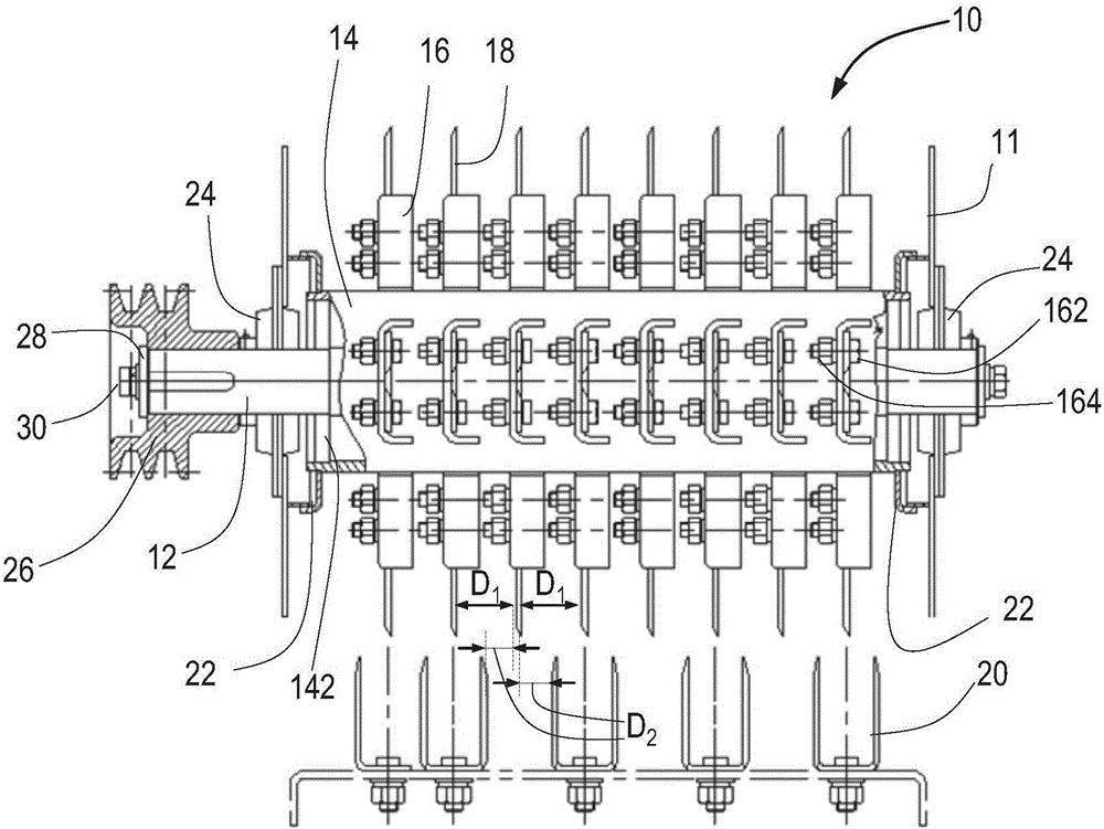
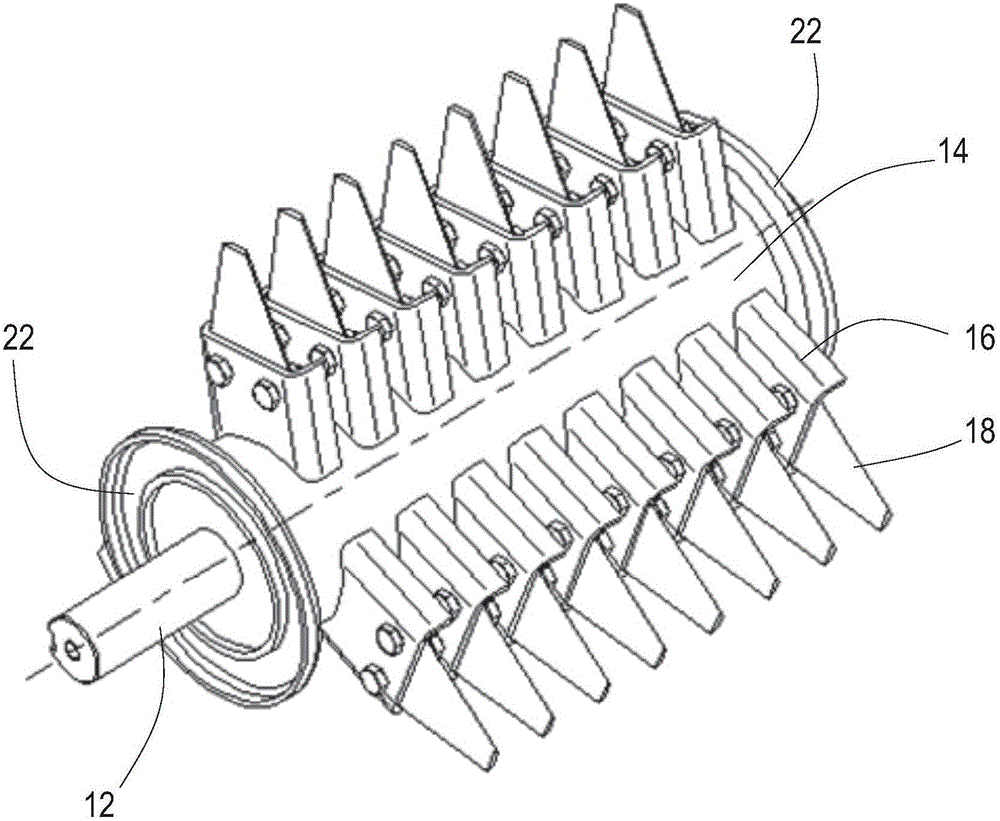
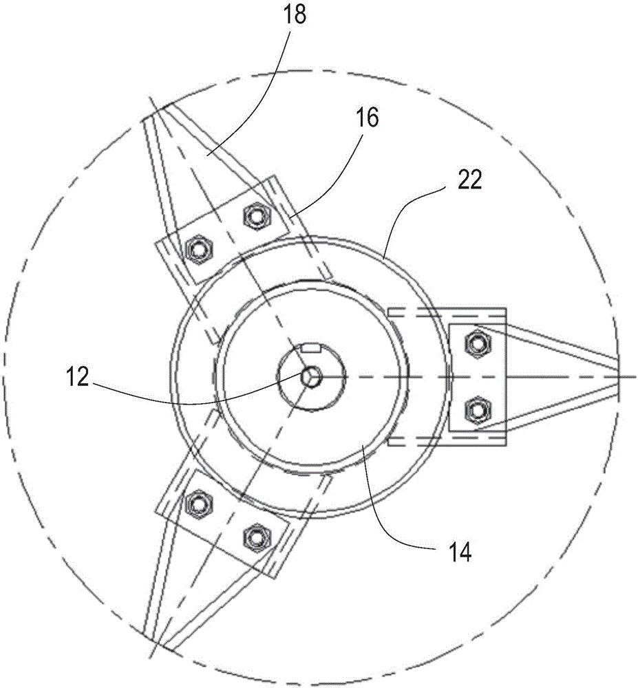
[0022] like figure 1 As shown, a partially cut-away side view of a grain harvester chopping device 10 according to the present invention is shown. Grain harvester chopping device according to the present invention comprises rotating shaft 12, around rotating shaft 12 relatively fixedly arranged drum 14, along the circumferential direction of drum 14 evenly arranged on the outer wall of drum 14 at multiple rows of knife seats 16 , a movable blade 18 disposed in each of the rows of knife seats 16 and a fixed blade 20 disposed corresponding to the movable blade 18 . Here, the rotating shaft 12 can be in the form of a solid shaft, and of course it can also be in the form of a hollow shaft. The dru...


PUM


Abstract

The invention relates to a grain harvesting machine and a chopping device thereof. The chopping device of the grain harvesting machine comprises a rotating shaft, a rotating drum, multiple rows of knife carriages, movable knife blades and fixed knife blades, wherein the rotating drum is arranged around the rotating shaft in a relatively fixed manner, the multiple rows of knife carriages are arranged on the external wall of the rotating drum along the circumferential direction of the rotating drum in a uniformly spaced manner, the movable knife blades are arranged in all of the multiple rows of knife carriages, and the fixed knife blades are arranged corresponding to the movable knife blades. Further, the spacing among adjacent movable knife blades is 34mm to 38mm, and the spacing among adjacent movable and fixed knife blades is 14mm to 18mm. According to the grain harvesting machine and the chopping device thereof, the movable and fixed knife blades, which are arranged according to the spacing, can enable straws of harvested crops achieve the optimal crushed effect during operation, so that the straws achieving the optimal crushed effect can be directly broadcast to farmland; and the crushed straws are plowed underground as an organic fertilizer through further plowing.

Description

technical field [0001] The invention relates to a straw crushing device, more particularly to a cutting device for harvesters used for grains such as wheat, rapeseed and rice. It also relates to a grain harvester using the chopping device. Background technique [0002] The technical background related to the present invention will be described below, but these descriptions do not necessarily constitute the prior art of the present invention. [0003] Usually, after the grain is harvested by the harvester, it is directly scattered on the field without being crushed, and the straw is long, which affects the plowing operation. In some places, farmers use the traditional method of burning straw and then carry out plowing operations. The disadvantage of this method is that on the one hand, it will cause serious air pollution, and sometimes it is difficult to control the flame, which is easy to cause fire; on the other hand, the organic matter inside the straw is destroyed after...

Claims


Application Information

Patent Timeline
Patent Type & Authority Applications(China)
IPC IPC(8): A01D43/08
CPCA01D43/08
Inventor 李煜王林陆胜安郑建何君
Owner ZOOMLION HEAVY MASCH CO LTD
Why Eureka
Try Eureka