
Minimally invasive bone plate device capable of achieving positional regulation of pressure

A technology of positioning adjustment and bone plate, applied in the field of medical devices, can solve the problems of a large impact on the patient's body recovery, long healing time, poor applicability, etc., to achieve the effect of improving bone setting effect, improving healing speed, and avoiding material waste.

Inactive Publication Date: 2016-12-07
潘秀岳
View PDF5 Cites 0 Cited by
  • Summary
  • Abstract
  • Description
  • Claims
  • Application Information

AI Technical Summary

Problems solved by technology

[0002] Bone plate fixation is a common method for orthopedics to treat fractures. After nearly a hundred years of development, implantable bone plates have made unprecedented progress in terms of materials and types. The traditional integrated design of bone plates can meet the needs of osteosynthesis , but due to the different nature of the patient's fracture, the size and thickness of the bone, the shape of the fracture, etc., it is difficult for the traditional bone plate to meet the needs of bone setting. Most of the current bone plates are specially designed according to the patient's bone, so the cycle is long and the cost is high. High, poor applicability, and the traditional bone plate needs to open an operation port according to the length of the bone plate during surgery. The large opening will take a long time to heal later, which will have a great impact on the recovery of the patient’s body. Therefore, an adjustable reduction surgery is needed. Minimally invasive bone plate device with positionable adjustable compression for post-recovery time

Method used


Image

  • Minimally invasive bone plate device capable of achieving positional regulation of pressure
  • Minimally invasive bone plate device capable of achieving positional regulation of pressure

Examples


Embodiment Construction

[0015] The following will clearly and completely describe the technical solutions in the embodiments of the present invention with reference to the accompanying drawings in the embodiments of the present invention. Obviously, the described embodiments are only some, not all, embodiments of the present invention.

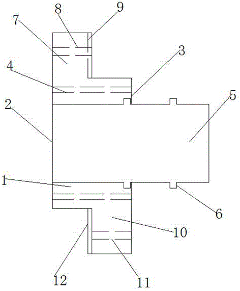
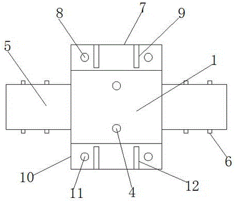
[0016] refer to Figure 1-2 , a minimally invasive bone plate device that can be positioned, adjusted and pressurized, comprising a bone plate unit 1, the bone plate unit 1 is made of a titanium alloy, one side of the bone plate unit 1 is an osteosynthesis surface 3, the The other side of the bone plate unit 1 is a fastening surface 2, the bone plate unit 1 is provided with a bone mounting hole 4, and the bone mounting hole 4 is located on the central axis of the bone plate unit 1, and the bone mounting hole 4 The number is 2, and the bone mounting hole 4 is a countersunk hole, the two ends of the bone plate unit 1 are respectively provided with a C-shaped cage 5, an...


PUM


Abstract

The invention discloses a minimally invasive bone plate device which can be positioned, adjusted and pressurized. It comprises a bone plate unit. There are bone mounting holes, and the two ends of the bone plate unit are respectively provided with a C-shaped cage, and two sets of adjustment blocks are provided on the C-shaped cage, and the first docking block is provided on the top of the fastening surface, and the first docking block is provided with Through holes, the first docking block is provided with a docking groove on the side close to the bone-synthetic surface, the second docking block is provided below the bone-synthetic surface, the second docking block is provided with threaded holes, and the second docking block is on the side close to the fastening surface Butt bumps are provided. The invention reduces the size of the surgical incision, improves the healing speed after operation, protects the health of the patient, prevents the bone plate from being too long or too short, avoids material waste, increases the strength of the bone plate, improves the osteosynthesis effect of the bone plate, and adjusts the bone plate The pressure between the bone and the bone can improve the bone setting effect and ensure the comfort of the patient.

Description

technical field [0001] The invention relates to the technical field of medical instruments, in particular to a minimally invasive bone plate device capable of positioning, adjusting and pressurizing. Background technique [0002] Bone plate fixation is a common method for orthopedics to treat fractures. After nearly a hundred years of development, implantable bone plates have made unprecedented progress in terms of materials and types. The traditional integrated design of bone plates can meet the needs of osteosynthesis , but due to the different nature of the patient's fracture, the size and thickness of the bone, the shape of the fracture, etc., it is difficult for the traditional bone plate to meet the needs of bone setting. Most of the current bone plates are specially designed according to the patient's bone, so the cycle is long and the cost is high. High, poor applicability, and the traditional bone plate needs to open an operation port according to the length of the ...

Claims


Application Information

Patent Timeline
Patent Type & Authority Applications(China)
IPC IPC(8): A61B17/80
CPCA61B17/8004A61B17/8023
Inventor 潘秀岳
Owner 潘秀岳
Learn More