
Flow guiding component of continuous type fluid separating device and continuous type fluid separating device

A technology of fluid separation and separation device, which is applied in the direction of liquid separation, separation methods, chemical instruments and methods, etc., and can solve problems such as blind ends in storage tanks and affecting separation effects

Active Publication Date: 2016-12-07
CHNA ENERGY INVESTMENT CORP LTD +1
View PDF5 Cites 1 Cited by
  • Summary
  • Abstract
  • Description
  • Claims
  • Application Information

AI Technical Summary

Problems solved by technology

[0005] In view of this, the object of the present invention is to propose a flow guide assembly and a continuous fluid separation device for a continuous fluid separation device, so as to solve the problems of existing gravity separation storage tanks with blind ends during gravity separation, which affect the separation effect, etc.

Method used


Image

  • Flow guiding component of continuous type fluid separating device and continuous type fluid separating device
  • Flow guiding component of continuous type fluid separating device and continuous type fluid separating device

Examples


Embodiment Construction

[0029] In order to make the object, technical solution and advantages of the present invention clearer, the present invention will be described in further detail below in conjunction with specific embodiments and with reference to the accompanying drawings. Wherein the same components are denoted by the same reference numerals. It should be noted that the words "front", "rear", "left", "right", "upper" and "lower" used in the following description refer to directions in the drawings. The terms "inner" and "outer" are used to refer to directions toward or away from, respectively, the geometric center of a particular component.

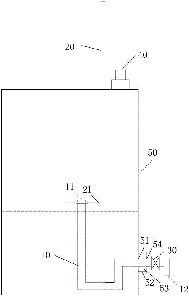
[0030] figure 2 It is a schematic diagram of a continuous fluid separation device used in a specific embodiment of the present invention. Such as figure 2 As shown, the guide assembly of the continuous fluid separation device includes: a guide pipe 10 and a guide rod 20 .

[0031] The draft tube 10 includes an inlet section 11 and an outlet sectio...


PUM


Abstract

The invention discloses a flow guiding component of a continuous type fluid separating device and the continuous type fluid separating device. The flow guiding component comprises a flow guiding pipe and a flow guiding rod, wherein the flow guiding pipe comprises an inlet section and an outlet section; the inlet section is used for guiding fluid into the flow guiding pipe; the outlet section is used for guiding out the fluid in the flow guiding pipe; the inlet section of the flow guiding rod is fixed on the flow guiding rod; the flow guiding rod can drive the inlet section to move along with the upper fluid level of the fluid. The flow guiding component and the continuous type fluid separating device disclosed by the invention have the advantages that the problems that the separating effect is influenced due to the blind end of the existing flow guiding component and separating device in gravity separation and the like are solved.

Description

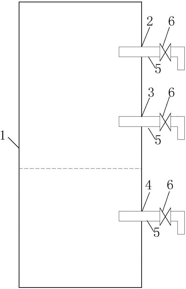
technical field [0001] The invention relates to material conveying equipment, and more specifically, to a flow guide assembly of a continuous fluid separation device and the continuous fluid separation device. Background technique [0002] Gravity separation is to use the immiscibility between the first medium and the second medium and the difference in density to form the first medium layer and the second medium layer through static separation. Gravity separation is a simple and effective separation method. [0003] figure 1 It is a schematic diagram of a gravity-separated storage tank adopted in the prior art. Such as figure 1 As shown, the storage tank for gravity separation includes a storage tank 1, a first notch 2, a second notch 3, and a third notch 4 arranged on the storage tank 1, and each notch protrudes one for communicating with the storage tank. Conduits 5 inside and outside the tank 1 and valves 6 that control the opening and closing of the conduits 5. The...

Claims


Application Information

Patent Timeline
Patent Type & Authority Applications(China)
IPC IPC(8): B01D17/025
CPCB01D17/0208
Inventor 陈秀刚于洪林李伟涛王利民
Owner CHNA ENERGY INVESTMENT CORP LTD
Learn More