
A combined air filter

An air filter and combined technology, applied in the field of combined air filters, can solve the problems of limited use angle, reduced filtering accuracy, waste of resources, etc., to achieve a wide range of applications, reduce replacement times, and increase use. effect of life

Active Publication Date: 2019-05-28
CLFG LONGHAI ELECTRONICS GLASS
View PDF7 Cites 0 Cited by
  • Summary
  • Abstract
  • Description
  • Claims
  • Application Information

AI Technical Summary

Problems solved by technology

However, the design of most air filters only uses one of the principles. This design can meet the needs of some small equipment, such as vehicle engines, etc., but in some occasions it cannot meet the filtration accuracy, or cannot Realize the high efficiency of filtration, causing problems such as waste of resources, such as air filters installed on large industrial machinery
[0003] In large-scale industrial machinery, the working environment is harsh, and the gas composition to be filtered is more complex and diverse, especially it may contain many large particles, so the air filter designed with a single principle, such as an ordinary filter type It is difficult for the air filter to filter it clean, and a large amount of large particles contained in it will easily cause the filter screen to be clogged. This will not only reduce the filtration accuracy, but also require frequent replacement of the filter element, resulting in waste of resources and environmental pollution.
[0004] Chinese patent "CN104131860B" discloses a "labyrinth oil-gas separation chamber equipped with a turbine", which adopts a combined oil-gas filter device with a labyrinth oil-gas separation structure and a filter element, which cannot meet the requirements of fixed industrial machinery used indoors. Requirements for waste gas environmental indicators
The first is that the filter element is set at the front of the labyrinth oil-gas separation structure. For oil and gas containing large-particle pollutants, the large-particle pollutants will cause blockage of the filter element when they first pass through the filter element, reducing the filtering effect and requiring frequent replacement of the filter element. The service life of the device is short and the cost is high; the second is that the baffle of the labyrinth oil-gas separation structure is set horizontally, and the oil-gas passage contains vertical parts, which will cause the condensed oil particles to stay on the baffle, especially when the baffle is used The tooth-shaped structure makes it more difficult for the oil particles to be recovered from the oil return tank; the third is that when the turbine cools the oil and gas, it is difficult to avoid condensed water, and the condensed water is also easy to stay on the baffle when it flows into the labyrinth oil-gas separation structure. It is difficult to discharge, which will have a bad impact on the filtering effect; Fourth, the use angle is very limited, and the installation method of the labyrinth oil-gas separation structure baffle makes the device unable to be installed obliquely, otherwise the cooling and condensed oil particles will easily converge on the baffle and At the angle of the side wall, long-term use will cause a large amount of oil particles to accumulate in this part, which will narrow the air path and affect the filtering effect; fifth, the replacement of the filter requires the device to be completely disassembled, and maintenance is very difficult

Method used


Image

  • A combined air filter
  • A combined air filter
  • A combined air filter

Examples


Embodiment 1

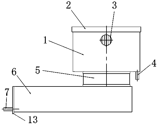
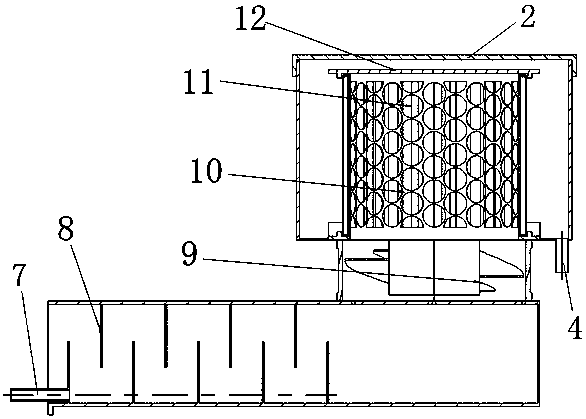
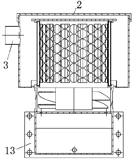
[0031] Such as Figures 1 to 4 As shown, a combined air filter is composed of an oil-gas separation tube 6 and a filter; the oil-gas separation tube 6 is a square tube with one end open and the other end closed, and the upper tube wall and the lower tube wall are close to the open end. Several vertical baffles 8 are evenly fixed and connected, and the baffles 8 on the upper pipe wall and the lower pipe wall are arranged alternately in the horizontal direction. Separation passage; the lower part of the baffle plate 8 arranged on the lower pipe wall is also provided with a through hole, and the lower part of the open end of the oil-gas separation pipe 6 is also provided with an oil outlet hole 7 . The length of the baffle plate 8 is equal to the width of the oil-gas separation pipe 6 . The through holes at the bottom of the baffle plate 8 are circular holes with equal diameters, and the axes of all the through holes are collinear. All the through holes and the oil outlet hole ...

Embodiment 2

[0040] The main structure is the same as the above-mentioned embodiment 1, the difference is that the oil outlet direction of the oil outlet hole 7 is toward the bottom of the oil-gas separation pipe 6, so that the separated oil can be directly recovered for further processing, and it is suitable for waste oil and will not be repeated. Take advantage of situations where only the emissions need to be cleaned.


PUM


Abstract

A combined air filter, which is composed of an oil-gas separation tube and a filter; the oil-gas separation tube is a square tube with one end open and the other end closed. Vertical baffle plate; the lower part of the baffle plate arranged on the lower pipe wall is also provided with a through hole, and an oil outlet hole is also provided at the lower part of the open end of the oil-gas separation pipe; the upper pipe wall of the oil-gas separation pipe near the closed end is connected with a wind The machine casing is provided with a fan inside the fan casing; the filter includes a filter casing arranged on the upper part of the fan casing and communicated with the fan casing, the upper end of the filter casing is covered with a filter cover plate, There is an exhaust hole on the side wall of the filter housing; an inner bracket is arranged inside the filter housing, and a filter screen in a cylindrical structure is provided on the inner bracket. The lower end of the filter screen is the air inlet end and is connected with The upper end of the fan housing is airtightly connected. The invention adopts a combined structure, can realize two times of filtering, and has good filtering effect.

Description

technical field [0001] The invention relates to an air filter, in particular to a combined air filter. Background technique [0002] At present, in the existing technical field, air filters are designed using the following five effects: interception effect, inertial effect, diffusion effect, gravity effect and electrostatic effect. However, the design of most air filters only uses one of the principles. This design can meet the needs of some small equipment, such as vehicle engines, etc., but in some occasions it cannot meet the filtration accuracy, or cannot Realize the high efficiency of filtration, causing problems such as waste of resources, such as air filters installed on large industrial machinery. [0003] In large-scale industrial machinery, the working environment is harsh, and the gas composition to be filtered is more complex and diverse, especially it may contain many large particles, so the air filter designed with a single principle, such as an ordinary filte...

Claims


Application Information

Patent Timeline
Patent Type & Authority Patents(China)
IPC IPC(8): B01D50/00
CPCB01D50/20Y02A50/2351
Inventor 司东宏余永健董永祥马俊师树谦薛玉君李济顺
Owner CLFG LONGHAI ELECTRONICS GLASS
Learn More