Absorption tower technique for removing ammonia from gas through multi-segment spraying

A process method and absorption tower technology, applied in the field of absorption tower technology, can solve the problems of unreasonable gas distribution, shrinking contact area, large liquid droplets, etc., and achieve the effect of overcoming unreasonable gas distribution

Inactive Publication Date: 2016-12-07
天津深蓝宇节能减排技术有限公司
View PDF0 Cites 0 Cited by
  • Summary
  • Abstract
  • Description
  • Claims
  • Application Information

AI Technical Summary

Problems solved by technology

[0003] The saturator method is only suitable for the production of ammonium sulfate by absorbing ammonia in the gas with sulfuric acid, and its scope of application is narrow
The absorption tower method has a wide range of applications and is suitable for absorbing ammonia in gases with various acidic liquids, but it has the defects of gas-liquid drift and low absorption rate.
[0004] There are two reasons for the gas-liquid drift in the absorption tower: one is the unreasonable gas distribution; the other is the uneven distribution of the spray liquid
The reason for the low efficiency of the absorption tower is: the liquid droplets sprayed by the nozzle are large, unevenly distributed and gas-liquid drift, the large droplet leads to a small contact area; the uneven distribution and gas-liquid drift lead to a small contact area
The absorption rate of the absorption tower is low, so that it cannot handle the gas with high ammonia content, or it is difficult to meet the concentration requirements of the ammonia content of the gas after absorption

Method used


Image

  • Absorption tower technique for removing ammonia from gas through multi-segment spraying

Examples


Embodiment Construction

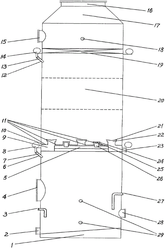
[0017] A multi-stage spraying method for absorbing towers for removing ammonia from gases will be described in detail below in conjunction with the accompanying drawings.

[0018] Referring to the accompanying drawings, the present invention is a multi-stage spray deammonization absorption tower, which consists of a tower body welded from bottom to top by tower base 1, tower body 20 and cone 17, a mist catcher 19, a It consists of an acid supply port 3, an overflow pipe 27, a liquid level gauge, a pressure gauge, a manhole I 28, a manhole II 15 and multi-stage spraying units installed in the tower body 20 at different heights.

[0019] Among them, the upper spraying unit is composed of a spraying device and a liquid breaker plate n 10, and the lowermost spraying unit is composed of a spraying device. The spraying devices are all installed outside the tower, and the nozzles extend into the tower from the outside. The spraying device is composed of a ring pipe I 8, a ring pipe ...


PUM


Abstract

The invention relates to an absorption tower technique for removing ammonia from gas through multi-segment spraying. According to the method, multiple segments of spraying units and a mist catcher are arranged in an absorption tower, the spraying units are arranged in a tower body in a segmented manner at different heights, and the following steps are implemented in the absorption tower: a, ammonia-rich gas enters a first segment of the absorption tower from an inlet and flows upwards and is uniformly distributed along the section of the absorption tower; b, the gas reaches the upper part of the absorption tower body after passing through all liquid stopping discs, and liquid drops entrained in the gas are captured when the gas passes through the mist catcher; c, a circulating liquid at the first segment of tower bottom is extracted out; d, the circulating liquid is sprayed into the absorption tower through annular pipes, small part of the liquid overflows to next segment in the absorption tower from an overflow plate, and multiple spray nozzles perform spraying simultaneously; e, the gas in each absorption segment in the absorption tower flows upwards, the liquid is sprayed downwards, so that ammonia in the ammonia-rich gas is absorbed by the circulating liquid, and ammonia is removed from the ammonia-rich gas. A one-segment or multi-segment spraying technology can be flexibly selected, ammonia in the gas is absorbed, and requirements are met.

Description

technical field [0001] The invention relates to a process for deammonizing chemical gas, in particular to an absorption tower process method for deammonizing chemical gas by using a multi-stage spraying device. Background technique [0002] In the prior art, there are two methods for removing ammonia from gas: one is the saturator method, and the other is the absorption tower method. [0003] The saturator method is only suitable for the production of ammonium sulfate by absorbing ammonia in the gas with sulfuric acid, and its scope of application is narrow. The absorption tower method has a wide range of applications and is suitable for absorbing ammonia in gases with various acidic liquids, but it has the defects of gas-liquid drift and low absorption rate. [0004] There are two reasons for the gas-liquid drift in the absorption tower: one is the unreasonable gas distribution; the other is the uneven distribution of the spray liquid. The reasons for the low efficiency o...

Claims


Application Information

Patent Timeline
Patent Type & Authority Applications(China)
IPC IPC(8): B01D53/18
CPCB01D53/18B01D2257/406
Inventor 李民凯
Owner 天津深蓝宇节能减排技术有限公司
Why Eureka
Try Eureka