Micro-fluidic chip and application thereof

A microfluidic chip and microfluidic chip technology, applied in the field of microfluidic control, can solve the problems of long time, low efficiency, high cost, manual configuration, etc., and achieve the effect of simple structure and convenient operation.

Active Publication Date: 2016-12-07
NANJING UNIV +1
View PDF4 Cites 23 Cited by
  • Summary
  • Abstract
  • Description
  • Claims
  • Application Information

AI Technical Summary

Problems solved by technology

[0003] When it is necessary to achieve the mixing of specific concentrations of different liquids on the microfluidic chip driven by centrifugal force for experiments and characteristic measurements, the existing solutions either use manual configuration, which takes a long time and is inefficient; or pu

Method used


Image

  • Micro-fluidic chip and application thereof
  • Micro-fluidic chip and application thereof
  • Micro-fluidic chip and application thereof

Examples


Embodiment Construction

[0029] Below in conjunction with accompanying drawing, technical scheme of the present invention is described further:

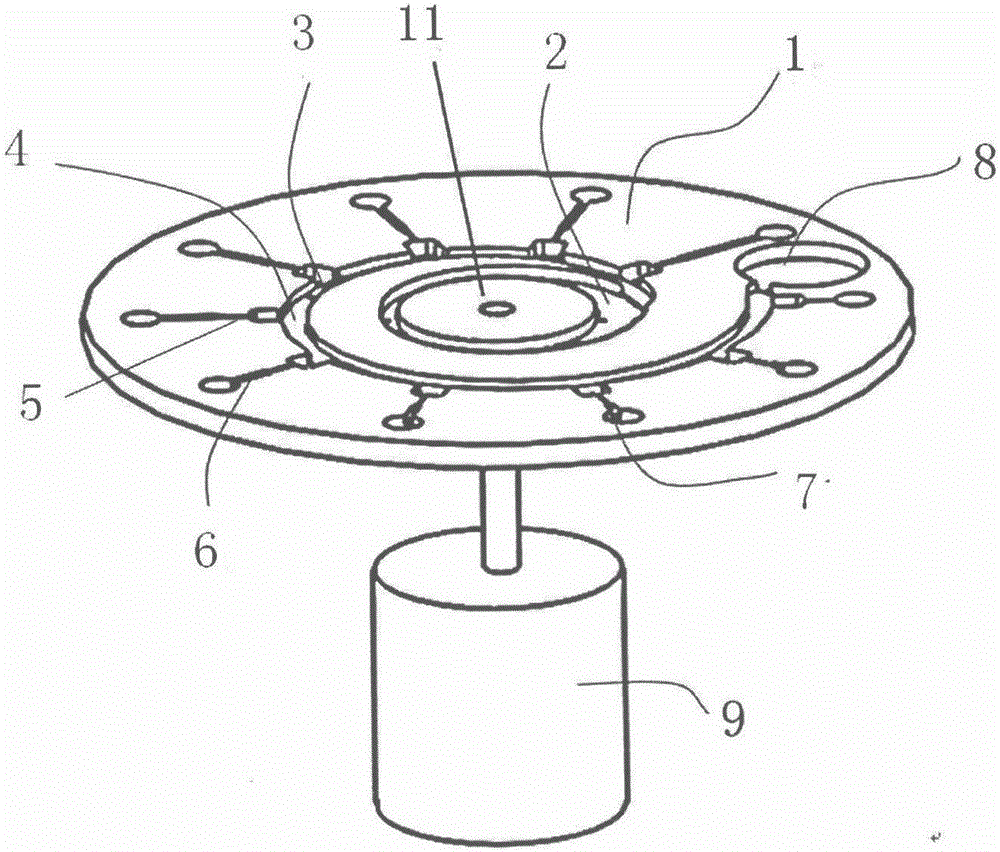
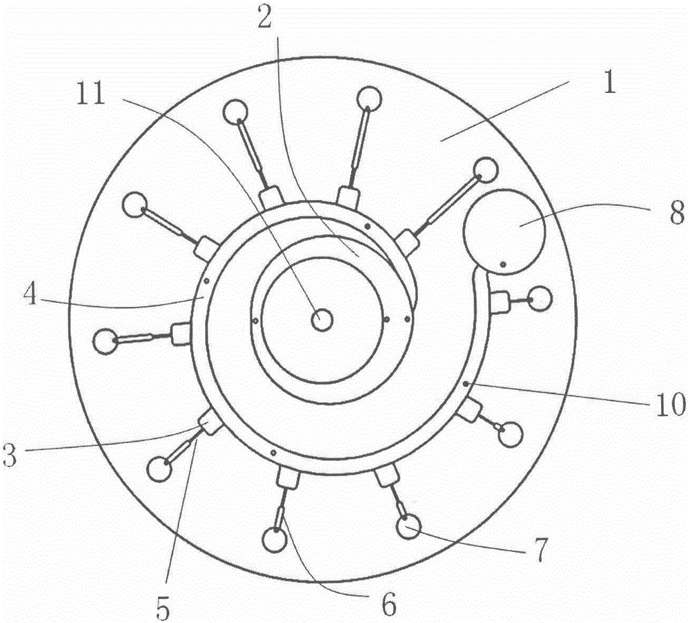
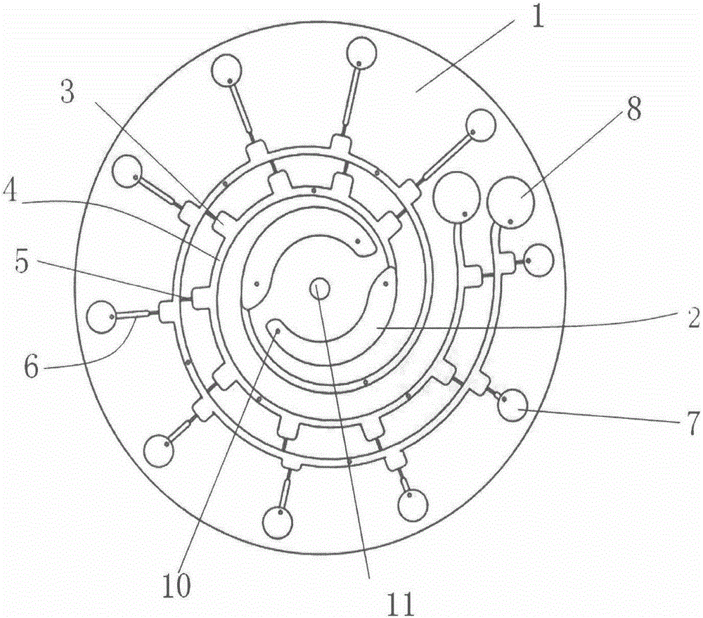
[0030] Such as figure 1 , figure 2 As shown, it is a microfluidic chip of the present invention. A spiral channel is provided on the chip body, and corresponding sample chambers, spiral channels, waste liquid chambers, metering chambers, microvalves, microfluidic channels and liquid mixing chambers are provided. The sample chamber is located near the center of the chip, and the waste liquid chamber is located near the edge of the chip. The spiral channel has a proximal end and a distal end, the proximal end communicates with the sample chamber, and the distal end communicates with the waste liquid pool. The metering chambers are distributed on the outside of the spiral channel along the spiral channel and communicate with the spiral channel. A microvalve is connected to the outside of each metering chamber; the microfluidic channels respectively open to th...


PUM


Abstract

The invention discloses a micro-fluidic chip, which can realize automatic releasing of samples in a plurality of parallel reaction channels and gradient type concentration control. The micro-fluidic chip rotates on a centrifugal force platform and the speed is adjusted, so that the samples in sample rooms enter spiral channels and flow in the spiral channels; the sequence and volume of the samples entering a liquid mixing room are controlled through adjusting the magnitude of a centrifugal force and a size structure of a metering valve. The invention further discloses a method based on the device, and a micro-fluidic chip structure corresponding to a plurality of types of liquid; the micro-fluidic chip structure comprises the plurality of sample rooms and the plurality of spiral channels. By adjusting the magnitude of the centrifugal force on the micro-fluidic chip, a multi-sample automatic releasing and gradient type concentration control device on the micro-fluidic chip is realized; the micro-fluidic chip is simple in structure and convenient to operate.

Description

technical field [0001] The invention relates to the field of microfluidic technology, in particular to a device and method for automatically injecting samples from multiple parallel reaction channels on a microfluidic chip and stepwise concentration control. Background technique [0002] The microfluidic chip driven by centrifugal force uses the centrifugal force generated by the microfluidic chip during circular motion as the driving force of the liquid flow, and adjusts and controls the dynamic characteristics of the fluid by changing the chip rotation speed and designing different channel configurations. . Centrifugal force drive is a relatively unique technology in microfluidic drive technology. Compared with other microfluidic drive methods, it has the advantages of convenient processing, low cost, high integration, high throughput, and no pulsation in fluid flow. The range of centrifugal force driving is wide, and the whole chip can be driven at the same time. The dri...

Claims


Application Information

Patent Timeline
IPC IPC(8): B01L3/00B01F3/08B01F13/00
CPCB01L3/502707B01L3/502715B01L3/502723B01L3/50273B01L3/502738B01L2400/0688B01L2400/0409B01L2300/0861B01L2300/0864B01L2300/0883B01F23/40B01F33/301B01F33/3017
Inventor 王光辉李忠文张冬莹张旭苹其他发明人请求不公开姓名
Owner NANJING UNIV
Why Eureka
Try Eureka