A crystallizer structure and cooling method inside the crystallizer

A cooling method and crystallizer technology, applied in the field of iron and steel metallurgy, can solve the problems of slow cooling molten steel, poor adaptability, and high maintenance costs, and achieve the effects of reducing molten steel superheat, simple and reasonable structure, and reducing temperature gradients

Active Publication Date: 2018-11-23
LAIWU STEEL YINSHAN SECTION CO LTD
View PDF4 Cites 1 Cited by
  • Summary
  • Abstract
  • Description
  • Claims
  • Application Information

AI Technical Summary

Problems solved by technology

Electromagnetic stirring technology utilizes the electromagnetic force induced in the liquid phase cavity of the slab to strengthen the movement of molten steel in the liquid phase cavity, which can break the dendrites and prevent the growth of columnar crystals. The rotational motion caused by electromagnetic stirring can also accelerate the casting slab. The convective heat transfer from the molten steel with high superheat in the center to the solidified billet shell, but due to the skin effect of the induced current, the electromagnetic stirring can only stir the molten steel in a small range, which will make it difficult to accurately control the position of the electromagnetic stirring and poor adaptability , high maintenance costs, slow cooling of molten steel, etc., and some old-fashioned continuous casting machines cannot install electromagnetic stirring devices at the mold position due to limited space
Mold feeding steel belt technology is to feed the cold steel belt into the mold to absorb the superheat of molten steel, but the line feeding equipment occupies a large area, and the slag on the mold liquid surface caused by the steel belt feeding process will pollute the steel. liquid etc.

Method used


Image

  • A crystallizer structure and cooling method inside the crystallizer
  • A crystallizer structure and cooling method inside the crystallizer
  • A crystallizer structure and cooling method inside the crystallizer

Examples


Embodiment 1

[0044] Embodiment 1: A cooling device built into a slab crystallizer.

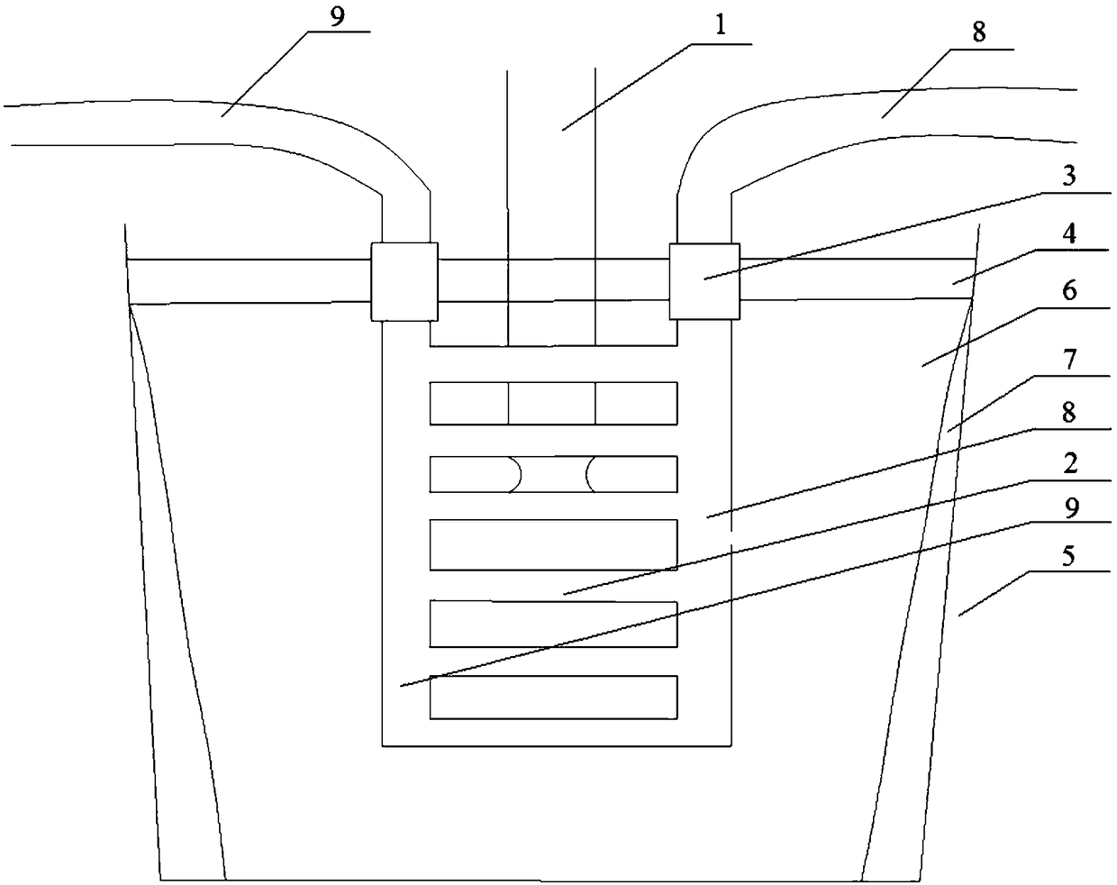
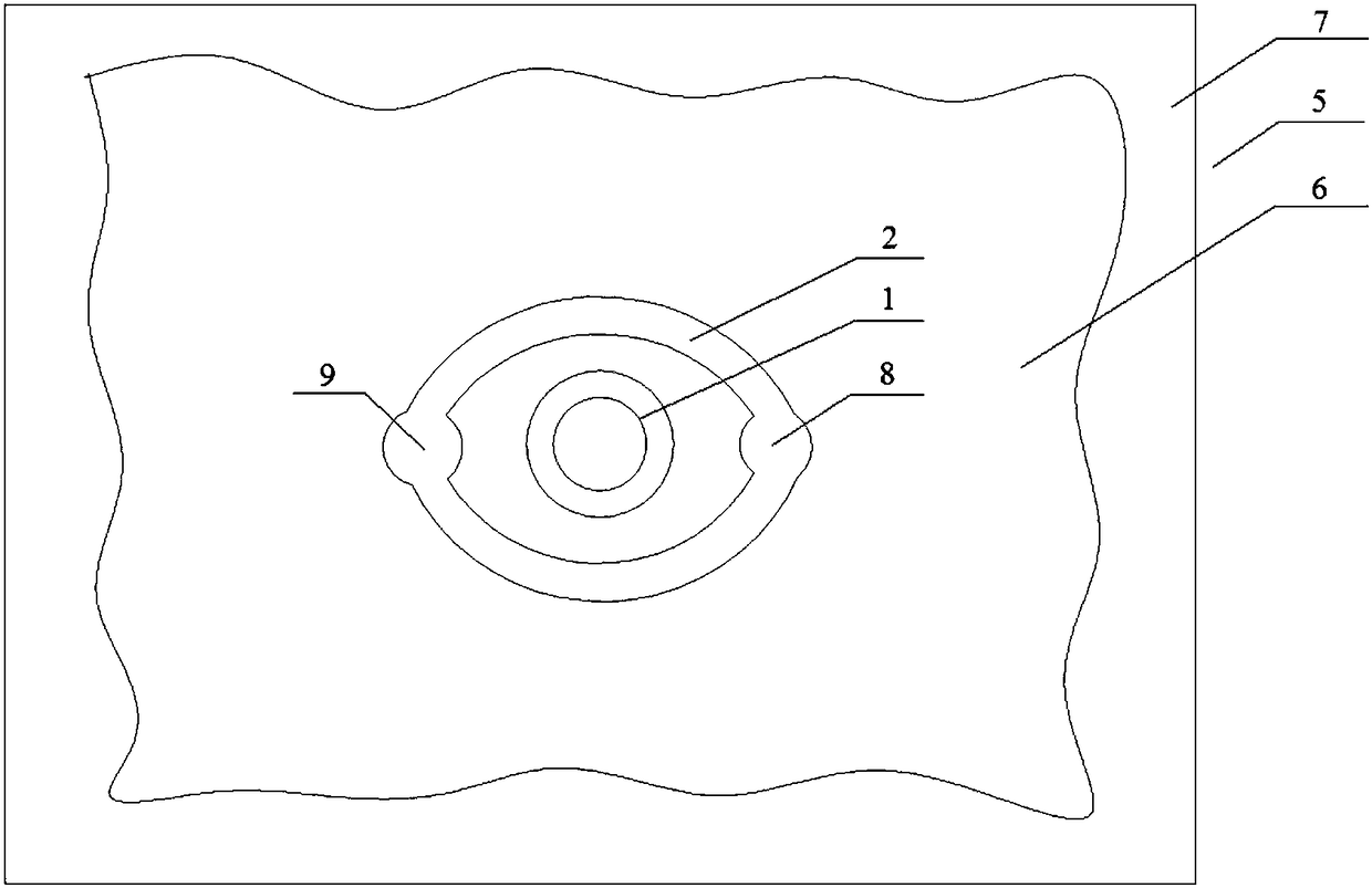
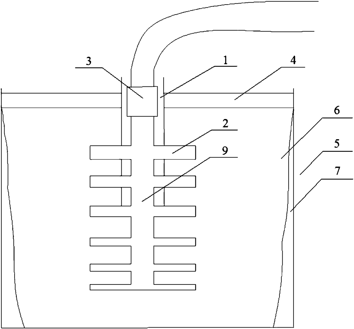
[0045] A cooling device built into the slab crystallizer, such as Figure 1-3 As shown, the billet size is 160mm×1260mm, and 10 elliptical annular pipes are arranged in the crystallizer 5 to form a cooling device. The inner diameter of the first circular pipe at the upper part of the cooling device is 0.8mm, and the inner diameter of the last circular pipe at the lower part is 0.4mm. , the inner diameter of the circular tube decreases from top to bottom, the wall thickness of the circular tube is 5mm, and the water flow rate in the circular tube is 0.4m / s. The parts where the water inlet pipe 8 and outlet pipe 9 of the cooling device are in contact with the mold slag 4 need to be wrapped with heat insulating components 3 In order to avoid the cooling effect of this device on the mold powder 4, the pipe material is steel, and after the cooling water system is connected from the outside of the crystallizer 5...

Embodiment 2

[0046] Embodiment 2: A cooling device built into a billet crystallizer.

[0047] A cooling device built into the billet crystallizer, such as Figure 1-3 As shown, the size of the billet is 220mm×220mm. Three circular pipes are arranged in the crystallizer 5 to form a cooling device. The inner diameter of the first circular pipe on the upper part of the cooling device is 0.9mm, and the inner diameter of the last circular pipe on the lower part is 0.5mm. , the inner diameter of the circular tube decreases from top to bottom, the wall thickness of the circular tube is 6mm, and the water flow rate in the circular tube is 0.5m / s. In order to avoid the cooling effect of this device on the mold powder 4, the material of the pipeline is steel, and after being connected to the cooling water system from the outside, the water circulates in the water inlet pipe 8, the intermediate connecting pipe 2, and the water outlet pipe 9, so as to reduce the The effect of the superheat of molten ...

Embodiment 3

[0048] Embodiment 3: A cooling device built into the slab crystallizer.

[0049] A cooling device built into the slab crystallizer, such as Figure 1-3 As shown, the size of the billet is 300mm×1800mm. Six circular pipes are arranged in the crystallizer 5 to form a cooling device. The inner diameter of the first round pipe at the upper part of the cooling pipe group is 1.5mm, and the inner diameter of the last round pipe at the lower part is 1mm. , the inner diameter of the round tube decreases from top to bottom, the wall thickness of the round tube is 8mm, and the water flow rate in the round tube is 0.8m / s. In order to avoid the cooling effect of this device on the mold powder 4, the material of the pipeline is steel, and after being connected to the cooling water system from the outside, the water circulates in the water inlet pipe 8, the intermediate connecting pipe 2, and the water outlet pipe 9, so as to reduce the The effect of the superheat of molten steel. During th...


PUM


Abstract

The invention provides a cooling device, a crystallizer structure adopting the cooling device and a cooling method for the interior of a crystallizer. The cooling device comprises a water inlet pipe, a water outlet pipe and a middle connecting pipeline. The water inlet pipe and the water outlet pipe communicate with the middle connecting pipeline. Cooling working media are introduced into the cooling device and can cool molten steel in contact with the outer portion of the cooling device; and the temperature difference between the molten steel and the cooling working media is large, the flowing speed of the motel steel nearby a submersed nozzle is high, convective heat transfer is quick, and a good cooling effect can be achieved. According to the crystallizer structure, the cooling device and the cooling method for the interior of the crystallizer in the scheme, the traditional continuously cast blank cooling manner from the outside to the inside is changed, and the molten steel is cooled mainly through the middle connecting pipeline in the crystallizer; and the structure is simple and reasonable, the temperature gradient between a solidification front of a cast blank and a liquid core of the cast blank can be reduced, and the function of reducing the degree of superheat of the molten steel in the casting process is achieved.

Description

technical field [0001] The invention belongs to the technical field of iron and steel metallurgy, in particular, the invention relates to a crystallizer structure and a cooling method inside the crystallizer. Background technique [0002] The traditional continuous casting slab cooling and solidification method is from the surface to the inside. There is a large temperature gradient between the slab solidification front and the slab liquid core. According to the selected crystallization theory and crystallography Based on the theory of preferred growth, inherent defects such as segregation and developed columnar crystals will inevitably occur during the solidification process of the slab, and problems such as central shrinkage cavity, porosity, and segregation may occur in the center of the slab. Low superheat pouring is an effective way to solve the above problems. A large number of equiaxed crystal nuclei will be formed in the low superheat region close to the liquidus tem...

Claims


Application Information

Patent Timeline
Patent Type & Authority Patents(China)
IPC IPC(8): B22D11/055B22D11/04
CPCB22D11/04B22D11/055
Inventor 刘洪银陈永生刘成宝邹春锋倪培亮肖强袁鹏举亓伟伟郝帅孙建卫杨旭王孝科
Owner LAIWU STEEL YINSHAN SECTION CO LTD
Why Eureka
Try Eureka