
Rapid tool changing device

A tool changing device and fast technology, applied in positioning device, clamping, support, etc., can solve the problems of low production efficiency, long time consumption, long time of tool replacement, etc., and achieve the effect of improving production efficiency and speed of tool change

Active Publication Date: 2016-12-07
ZHEJIANG TOMAN ZHIZAO TECH CO LTD
View PDF8 Cites 4 Cited by
  • Summary
  • Abstract
  • Description
  • Claims
  • Application Information

AI Technical Summary

Problems solved by technology

[0003] However, although the performance of various cutting processing equipment has been extensively and greatly improved, in many occasions, especially in occasions with high cutting requirements, such as the cutting of bearing rings, it is often necessary to replace the tool
Due to the limitation of the performance characteristics of the existing cutting processing device, it takes a long time to replace the cutting tool, especially for the bearing ring cutting processing device, which also requires precise fine-tuning of the cutting tool, which takes a long time and lowers the production efficiency

Method used


Image

  • Rapid tool changing device
  • Rapid tool changing device
  • Rapid tool changing device

Examples


Embodiment Construction

[0026] In order to make the above objects, features and advantages of the present invention more comprehensible, specific implementations of the present invention will be described in detail below in conjunction with the accompanying drawings. In the following description, numerous specific details are set forth in order to provide a thorough understanding of the present invention. However, the present invention can be implemented in many other ways different from those described here, and those skilled in the art can make similar improvements without departing from the connotation of the present invention, so the present invention is not limited by the specific embodiments disclosed below.

[0027] It should be noted that when an element is referred to as being “fixed” to another element, it can be directly on the other element or there can also be an intervening element. When an element is referred to as being "connected to" another element, it can be directly connected to t...


PUM


Abstract

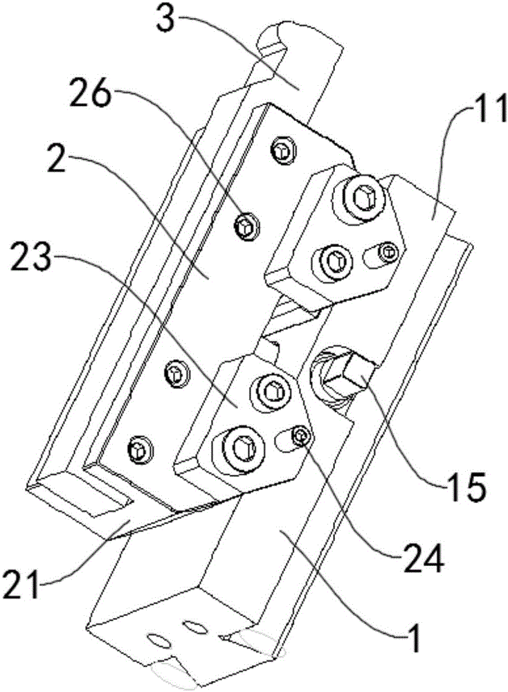
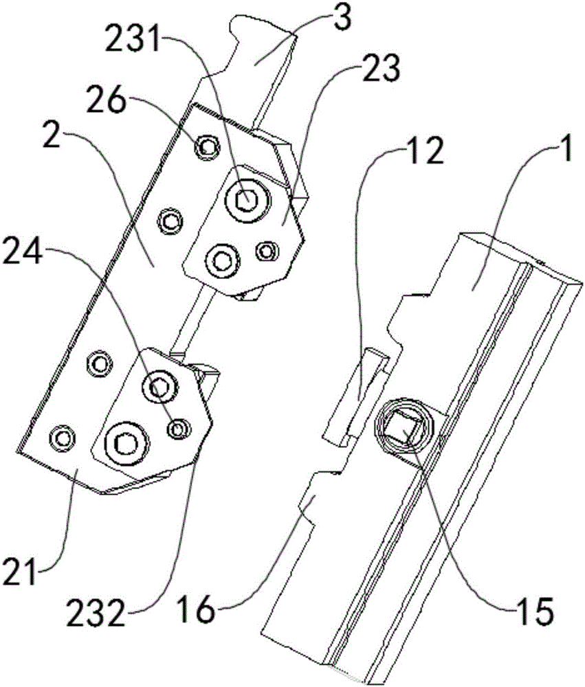
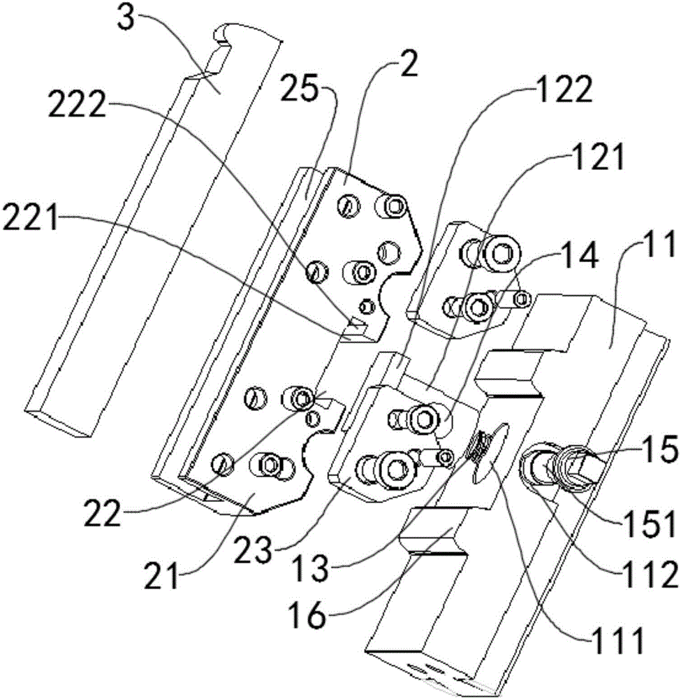
A rapid tool changing device comprises a fixed tool apron assembly, a movable tool apron assembly and a blade. The fixed tool apron assembly comprises a fixed tool apron and clamping blocks. The clamping blocks are adjustably fixed to the fixed tool apron. The movable tool apron assembly comprises a movable tool rest and a clamping slot. The clamping slot is fixedly arranged on the movable tool rest. The fixed tool apron assembly and the movable tool apron assembly are fixedly connected in the manner that the clamping blocks and the clamping slot are connected in a clamped manner. The blade is fixed to the movable tool rest. Each clamping block comprises a clamping body and a clamping head. The clamping bodies are fixedly and adjustably fixed into the fixed tool apron. Each clamping head is fixedly arranged at the end, extending out of the fixed tool apron, of the corresponding clamping body. The fixed tool apron is provided with a first installation hole and a second installation hole. The clamping bodies are installed in the first installation hole. A rotatable clamping rod is installed in the second installation hole. According to the rapid tool changing device, tool changing is rapid and convenient, extra fine adjustment is not needed, the tool changing speed is increased, and the production efficiency is improved.

Description

technical field [0001] The invention relates to a quick tool changing device, in particular to a quick tool changing device for a bearing ring cutting and processing device. Background technique [0002] Cutting processing equipment is a machine tool that mainly uses turning tools to turn rotating workpieces. In cutting processing, drills, reamers, reamers, taps, dies and knurling tools can also be used for corresponding processing. Ordinary machine tools have experienced a history of nearly two hundred years. With the development and comprehensive application of electronic technology, computer technology and automation, precision machinery and measurement technologies, a new type of machine tool integrating mechatronics - CNC machine tools has been produced. CNC cutting is the abbreviation of digital program-controlled cutting. It integrates the characteristics of universal cutting, high-precision precision cutting and high-efficiency special-purpose cutting. It is the larg...

Claims


Application Information

Patent Timeline
Patent Type & Authority Applications(China)
IPC IPC(8): B23Q3/00
CPCB23Q3/00
Inventor 陈成富
Owner ZHEJIANG TOMAN ZHIZAO TECH CO LTD
Learn More