
Assembly tool of engine flywheel bearing and protecting method of assembly tool

A technology for assembling tools and engines, applied in the direction of manufacturing tools, hand-held tools, etc., can solve the problems of hidden safety hazards, high labor intensity, low assembly efficiency, etc., and achieve the effect of improving assembly quality, reducing labor intensity and convenient operation.

Active Publication Date: 2016-12-07
GUANGXI YUCHAI MASCH CO LTD
View PDF9 Cites 0 Cited by
  • Summary
  • Abstract
  • Description
  • Claims
  • Application Information

AI Technical Summary

Problems solved by technology

Such an assembly method has high labor intensity and low assembly efficiency, and there are also potential safety hazards.

Method used


Image

  • Assembly tool of engine flywheel bearing and protecting method of assembly tool
  • Assembly tool of engine flywheel bearing and protecting method of assembly tool
  • Assembly tool of engine flywheel bearing and protecting method of assembly tool

Examples


Embodiment Construction

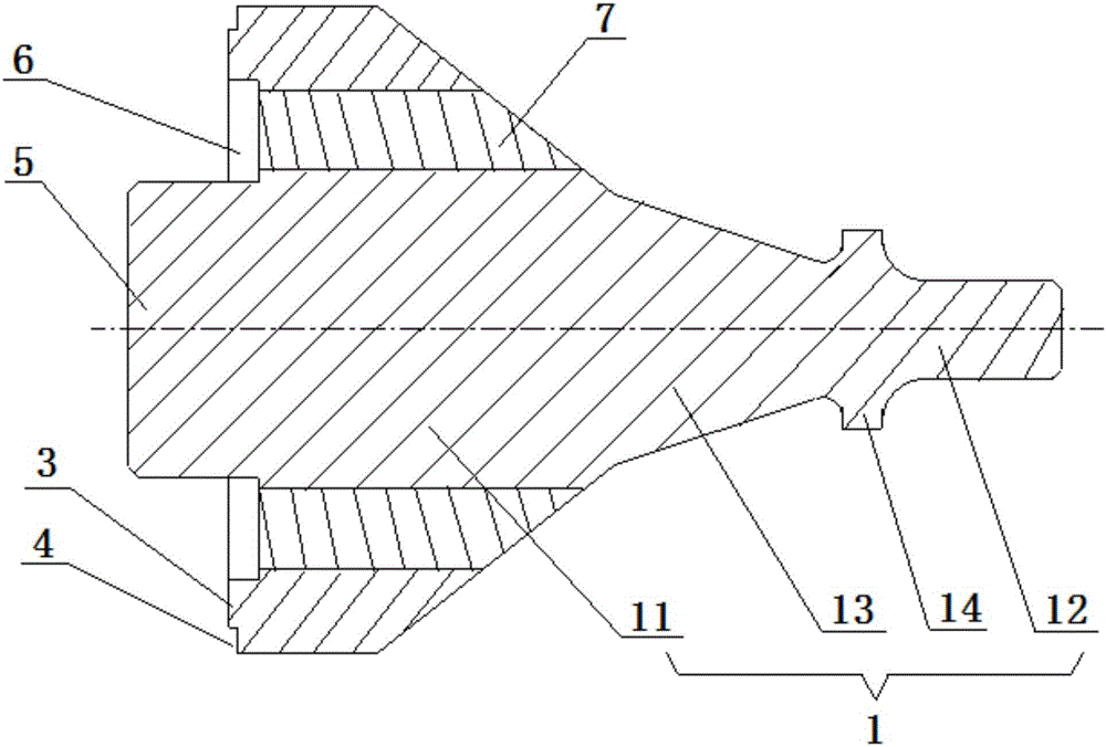
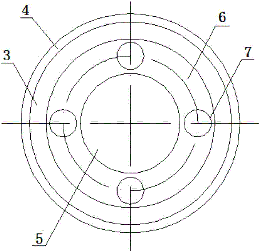
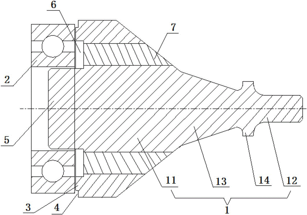
[0028] The present invention will be further described below in conjunction with the specific embodiments in the accompanying drawings.

[0029] refer to Figure 1-4 , the assembly tool of a kind of engine flywheel bearing of the present invention comprises the beating body 1 that is used for positioning and beating bearing 2, and the end face of this beating body 1 is circular, is provided with bearing 2 on one end face of this beating body 1 The flat cylindrical reference boss 3 whose outer ring size is suitable, one end face of its bearing 2 is in contact with the end face of the reference boss 3, and a height difference between the beating body 1 and the reference boss 3 forms a preventable The ring-shaped relief groove 4 where the beating body 1 interferes with the side wall of the bearing installation hole. During the installation of the bearing 2, when one end of the bearing 2 is parallel to the end face of the bearing installation hole, the bearing 2 continues to be in...


PUM


Abstract

The invention discloses an assembly tool of an engine flywheel bearing, comprising a knocking body for locating and knocking the bearing; the end surface of one end of the knocking body is provided with a flat-column-shaped reference boss adapted to the outer ring of the bearing in size; an annular avoiding groove capable of avoiding the interference between the knocking body and the side wall of a bearing mounting hole is formed by the height difference between the outer edge of the end surface of the knocking body and the reference boss; the reference boss is also provided with a cylindrical locating boss which is coaxially arranged with the reference boss and can be movably inserted to the inner ring of the bearing; an annular groove which is axially and inwards arranged along the edge of the outer side of the locating boss is formed in the reference boss close to one side of the locating boss; and a plurality of magnetic rods inserted from the bottom of the annular groove to the knocking body along the axial direction are uniformly distributed in the annular groove. The invention also discloses an assembly method of the engine flywheel bearing. The assembly tool is simple in structure, convenient to operate and capable of rapidly assembling the engine flywheel bearing and solving the problem of low bearing assembly efficiency.

Description

technical field [0001] The invention relates to the technical field of engine assembly, more specifically, it relates to an assembly tool and an assembly method of an engine flywheel bearing. Background technique [0002] In the engine (diesel engine) manufacturing industry, the assembly of engine parts will directly affect the performance and quality of the whole machine. During the engine assembly process, some parts need to be assembled on the body in the form of interference fit, especially for Assembly of bearings. At present, for the bearing assembly of the engine flywheel, it is usually first to take the bearing by hand or put the bearing on a tooling by hand, then beat the bearing or the tooling by hand, and finally assemble the bearing in place. Such an assembly method has high labor intensity and low assembly efficiency, and also has potential safety hazards. Therefore, a simple and labor-saving bearing assembly method becomes particularly important. Contents o...

Claims


Application Information

Patent Timeline
Patent Type & Authority Applications(China)
IPC IPC(8): B25B27/06B25B27/067
Inventor 袁冠臣杨靖益
Owner GUANGXI YUCHAI MASCH CO LTD
Learn More