A small hole extractor

An object and outer sleeve technology, applied in the field of extraction tools for objects in small holes, can solve problems such as difficult alignment, damage to objects, and difficult extraction of objects, and achieve the effect of improving work efficiency and flexible use

Active Publication Date: 2018-07-31
CHANGSHA UNIVERSITY OF SCIENCE AND TECHNOLOGY
View PDF6 Cites 0 Cited by
  • Summary
  • Abstract
  • Description
  • Claims
  • Application Information

AI Technical Summary

Problems solved by technology

[0004] Although the existing object extractor has played a certain effect when the object is extracted from a small hole, there are two situations where it is difficult to extract the object by using the existing object extractor: one is when the surface of the object is very smooth and cannot be sucked, The machine claw picker needs to exert a large clamping force to firmly clamp the object. During the pick-up process, there is a risk of dropping the object or destroying the object due to excessive clamping force, especially when the size of the object is not much different from the aperture. The operating space of the picker is severely limited, making it difficult to grab objects; second, when using the claw picker, the position of the picked object generally needs to be directly below the claw, so that the claw picker can Close the claws and grab the object, but when the object is close to the edge of the hole wall, the volume of the claw itself and the space required for expansion limit its picking action, making it difficult to align objects near the edge of the hole wall, making Objects tend to slip out of the claws during the fetching process, making it difficult to achieve the purpose of safely grabbing objects

Method used


Image

  • A small hole extractor
  • A small hole extractor
  • A small hole extractor

Examples


Embodiment Construction

[0032] The technical solution of the present invention will be further described below in conjunction with the accompanying drawings.

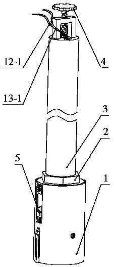
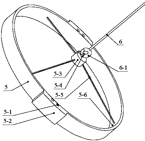
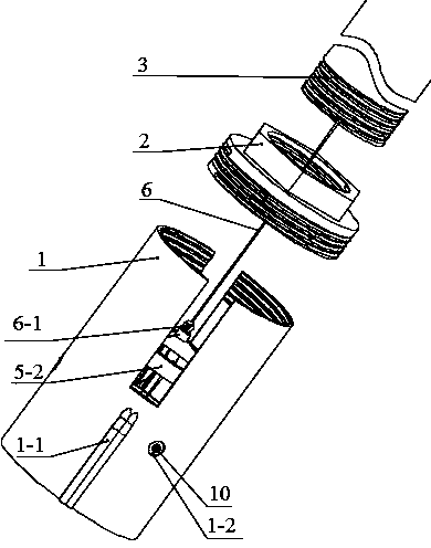
[0033] The invention relates to a small-hole object extractor, which mainly includes an object extractor and an auxiliary device. The pick-up device includes: connecting pipe 3, pull wire 6, handle 4, joint 2, inner sleeve 7, outer sleeve 1, elastic cloth 11, thin wire 9 and inner ring 5. The auxiliary device includes a camera 12 and a lighting lamp 13 . During the fetching process, firstly, the fetching device covers the fetched object 14, turns the handle 4 counterclockwise, the pull wire 6 pulls the inner ring 5 to move upwards and tightens the thin thread 9, so that the elastic cloth 11 runs along the lower end of the inner sleeve 7 Get close to the middle, then hold up the object 14 from below to realize the action of fetching. The following describes the implementation and features of the present invention step by step according to the...


PUM


Abstract

The invention discloses a small hole object grabbing device. Main parts comprise a connecting pipe, a pull wire, a handle, a joint, an inner sleeve, an outer sleeve, elastic fabric, a fine wire and an inner ring; the joint is used for connecting the connecting pipe with the outer sleeve; the handle comprises a thread and is mounted on the connecting pipe to form a spiral pair, the lower end of the handle is connected with the inner ring through the pull wire, and the inner ring can vertically move through the pull wire by rotating the handle; the inner sleeve is mounted in the outer sleeve through a screw, the elastic fabric is arranged on the outer wall of the inner sleeve, the fine wire is connected to the lower end of the elastic fabric in a penetrating manner, and through the handle and the inner ring, the fine wire can be tensioned and loosened; and when the sleeves cover a grabbed object, the handle is rotated, the pull wire pulls the inner ring to move upwards and tightens the fine wire, the elastic fabric is folded towards the middle along the lower end of the inner sleeve, object grabbing action is formed, an object is jacked up, object grabbing is achieved, and on the contrary, the object is abandoned. A camera and a lighting lamp are arranged in the object grabbing device, and object grabbing can be conveniently observed; and the object which has the certain volume and cannot be sucked can be flexibly grabbed from a small hole.

Description

technical field [0001] The invention discloses an object extraction tool, in particular to an object extraction tool in a small hole. Background technique [0002] In various municipal projects, maintenance of pipelines, and daily work, sometimes due to people's negligence, some valuable small objects are dropped into vertical small holes, and the dropped objects cannot be picked up directly, and tools must be used to extract items from the small holes . [0003] In order to solve this problem, a series of object fetchers have emerged on the market. At present, there are two main categories of fetchers on the market: one is to pick up objects by means of claws, that is, according to the principle of the rocker mechanism, the claws of the fetcher are closed towards the center, so as to grip objects and realize Another type of fetching device is to use the principle of suction, that is, to use a machine that can generate suction to suck objects and realize fetching. [0004...

Claims


Application Information

Patent Timeline
Patent Type & Authority Patents(China)
IPC IPC(8): B25J1/06
CPCB25J1/06
Inventor 彭潇潇毛聪张宇尘孔明慧徐天淳杨涌
Owner CHANGSHA UNIVERSITY OF SCIENCE AND TECHNOLOGY
Why Eureka
Try Eureka