Lower limb assistance mechanical outer skeleton

An exoskeleton and mechanical technology, applied in manipulators, program-controlled manipulators, manufacturing tools, etc., can solve the problems of poor movement stability of lower limbs, difficult to popularize and use, and expensive, and achieve convenient operation, improve energy utilization, manufacture and use. low cost effect

Inactive Publication Date: 2016-12-07
HOHAI UNIV CHANGZHOU
View PDF10 Cites 12 Cited by
  • Summary
  • Abstract
  • Description
  • Claims
  • Application Information

AI Technical Summary

Problems solved by technology

[0002] At present, in order to reduce human labor intensity and improve work efficiency, mechanization has become a necessary means. However, some existing mechanized equipment is limited by some external conditions and cannot effectively solve the problem of high-height and heavy-duty exercise. Existing exoskeleton technologies mostly use hydraulic drive. Expensive, not easy to promote and use
In the structure disclosed in the Chinese patent with the application number 201511019542.4, the driving method of the spring energy storag

Method used


Image

  • Lower limb assistance mechanical outer skeleton
  • Lower limb assistance mechanical outer skeleton
  • Lower limb assistance mechanical outer skeleton

Examples


Embodiment 1

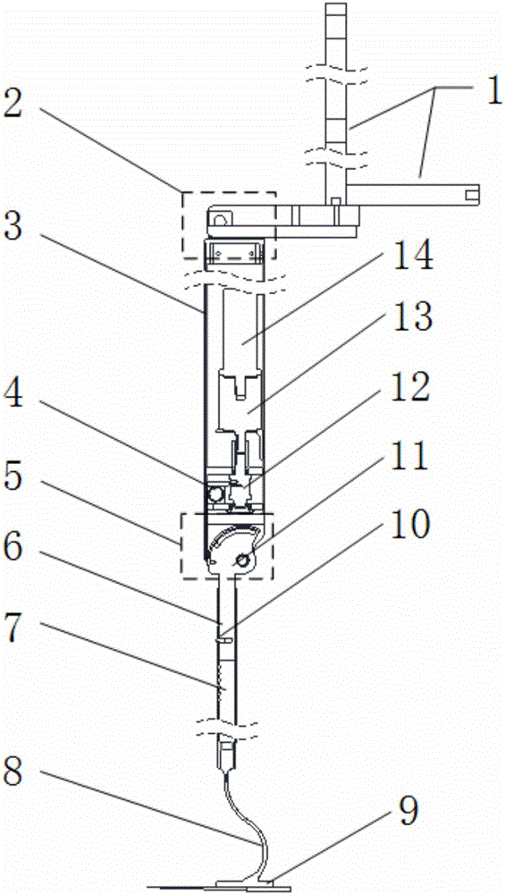
[0032] Such as figure 1 , 3 , Shown in 4, a kind of lower limb assist mechanical exoskeleton, it comprises:

[0033] back support 1;

[0034] thigh part 3, the top of the thigh part 3 is hinged with the back support 1 through the hip joint 2;

[0035] a calf part, the top of which is hinged to the bottom of the thigh part 3 via the knee joint 5;

[0036] Knee joint drive mechanism, the knee joint drive mechanism drives the knee joint 5 to move, so that the calf part rotates relative to the thigh part 3 through the knee joint 5;

[0037] The sole of the foot 9, the sole of the foot 9 is connected with the bottom of the calf part through the ankle joint.

[0038] Such as figure 1 As shown, the ankle joint is an elastic body ankle joint 8 capable of storing and releasing elastic potential energy, the top of the ankle joint is fixedly connected with the calf part, and the bottom of the ankle joint is fixedly connected with the sole of the foot 9 .

[0039] Wherein, the lower...

Embodiment 2

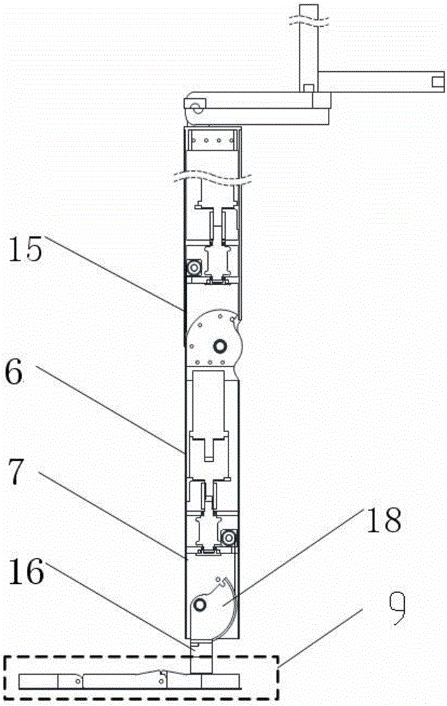
[0049] The structure of this embodiment is basically the same as that of Embodiment 1, the difference is: as Figure 2-4 As shown, the ankle joint is an external force-driven ankle joint 16, the sole of the foot 9 is hinged with the bottom of the lower leg through the external force-driven ankle joint 16, and it also includes driving the external force-driven ankle joint 16 to move The ankle joint drive mechanism that makes the sole 9 rotate relative to the calf part through the external force-driven ankle joint 16; wherein, the external force-driven ankle joint 16 and the knee joint 5 have the same structure, and the ankle joint drive mechanism and the knee joint drive The mechanism structure is the same, the bracket of the external force-driven ankle joint 16 is an ankle joint bracket, and the ankle joint bracket is fixedly connected to the top of the calf part, and the rotating body of the external force-driven ankle joint 16 is an ankle joint rotating body 18, and the ankle...


PUM


Abstract

The invention discloses a lower limb assistance mechanical outer skeleton. The lower limb assistance mechanical outer skeleton comprises a back support, a thigh part, a shank part, a knee joint driving mechanism and a foot sole. The top of the thigh part is hinged to the back support through a hip joint. The top of the shank part is hinged to the bottom of the thigh part through a knee joint. The knee joint driving mechanism drives the knee joint to move, and thus the shank part rotates relative to the thigh part through the knee joint. The foot sole is connected with the bottom of the shank part through an ankle joint. The lower limb assistance mechanical outer skeleton can enhance the high load and flexible movement ability of people and has the characteristics of being low in cost, convenient to use and simple to maintain.

Description

technical field [0001] The invention relates to a lower limb assist mechanical exoskeleton. Background technique [0002] At present, in order to reduce human labor intensity and improve work efficiency, mechanization has become a necessary means. However, some existing mechanized equipment is limited by some external conditions and cannot effectively solve the problem of high-height and heavy-duty exercise. Existing exoskeleton technologies mostly use hydraulic drive. Expensive, not easy to popularize and use. In the structure disclosed in the Chinese patent with the application number 201511019542.4, the driving method of the spring energy storage bouncing exoskeleton is that the motor drives the rope through the screw nut pair, and the other end of the rope is connected to the spring hook pressing part of the leg, so that the spring compresses and stores energy. After reaching a certain level, the elastic potential energy is triggered by the return poke rod to achieve th...

Claims


Application Information

Patent Timeline
IPC IPC(8): B25J9/00B25J9/10
CPCB25J9/0006B25J9/104
Inventor 王义斌陈娇董兴建李文唐启阳
Owner HOHAI UNIV CHANGZHOU
Why Eureka
Try Eureka